How to Use Conversor DC/DC Reductor: Examples, Pinouts, and Specs
Introduction
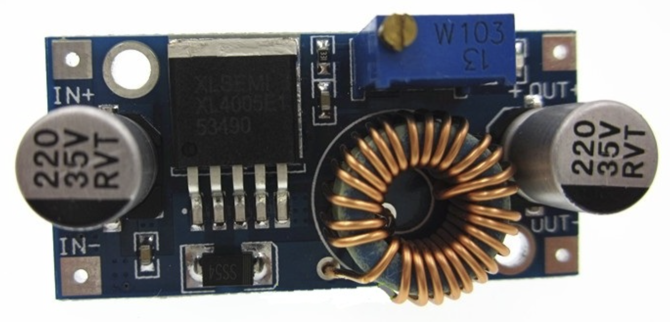
The Conversor DC/DC Reductor (Manufacturer Part ID: LM2596-V-5A) is a highly efficient DC/DC buck converter designed to step down voltage from a higher input level to a lower output level. This component is widely used in power supply circuits where efficient voltage regulation is required. It is capable of delivering up to 5A of output current, making it suitable for a variety of applications.
Explore Projects Built with Conversor DC/DC Reductor


Explore Projects Built with Conversor DC/DC Reductor
Common Applications and Use Cases
- Powering low-voltage devices from higher-voltage sources (e.g., 12V to 5V conversion)
- Battery-powered systems to regulate voltage
- Embedded systems and microcontroller projects
- LED drivers and motor controllers
- Industrial and automotive electronics
Technical Specifications
The following table outlines the key technical specifications of the LM2596-V-5A:
| Parameter | Value |
|---|---|
| Input Voltage Range | 4.5V to 40V |
| Output Voltage Range | 1.23V to 37V (adjustable) |
| Maximum Output Current | 5A |
| Efficiency | Up to 92% |
| Switching Frequency | 150 kHz |
| Output Voltage Ripple | ≤ 30 mV |
| Operating Temperature | -40°C to +85°C |
| Dimensions | 45mm x 20mm x 14mm |
Pin Configuration and Descriptions
The LM2596-V-5A module typically has the following pin configuration:
| Pin Name | Description |
|---|---|
| VIN | Input voltage pin. Connect the higher voltage source (e.g., 12V, 24V). |
| VOUT | Output voltage pin. Provides the regulated lower voltage (e.g., 5V, 3.3V). |
| GND | Ground pin. Connect to the ground of the input and output circuits. |
| ADJ (optional) | Adjustment pin for setting the output voltage (used in adjustable versions). |
Usage Instructions
How to Use the Component in a Circuit
Connect the Input Voltage (VIN):
- Attach the positive terminal of your power source to the VIN pin.
- Connect the negative terminal of your power source to the GND pin.
Set the Output Voltage (if adjustable):
- For adjustable versions, use the onboard potentiometer to set the desired output voltage.
- Measure the output voltage across the VOUT and GND pins using a multimeter.
Connect the Load:
- Attach the positive terminal of your load to the VOUT pin.
- Connect the negative terminal of your load to the GND pin.
Power On:
- Turn on the input power source. The module will regulate the input voltage to the desired output voltage.
Important Considerations and Best Practices
- Input Voltage Range: Ensure the input voltage is within the specified range (4.5V to 40V). Exceeding this range may damage the module.
- Heat Dissipation: For high current loads, the module may heat up. Use a heatsink or active cooling if necessary.
- Output Voltage Ripple: If low ripple is critical, consider adding additional filtering capacitors at the output.
- Polarity Protection: Double-check the polarity of the input and output connections to avoid damage.
- Load Current: Do not exceed the maximum output current of 5A to prevent overheating or failure.
Example: Using with Arduino UNO
The LM2596-V-5A can be used to power an Arduino UNO from a 12V source by stepping down the voltage to 5V. Below is an example circuit and code:
Circuit Connections
- Connect the VIN pin of the LM2596 module to the 12V power source.
- Connect the VOUT pin to the 5V pin of the Arduino UNO.
- Connect the GND pin of the module to the GND pin of the Arduino UNO.
Example Code
// Example code to blink an LED using Arduino UNO powered by LM2596-V-5A
// Ensure the LM2596 module is set to output 5V before connecting to Arduino.

const int ledPin = 13; // Built-in LED pin on Arduino UNO

void setup() {
  pinMode(ledPin, OUTPUT); // Set LED pin as output
}

void loop() {
  digitalWrite(ledPin, HIGH); // Turn the LED on
  delay(1000);               // Wait for 1 second
  digitalWrite(ledPin, LOW);  // Turn the LED off
  delay(1000);               // Wait for 1 second
}
Troubleshooting and FAQs
Common Issues Users Might Face
No Output Voltage:
- Cause: Incorrect input connections or insufficient input voltage.
- Solution: Verify the polarity and ensure the input voltage is within the specified range.
Output Voltage Not Stable:
- Cause: Insufficient filtering or excessive load current.
- Solution: Add additional capacitors at the output or reduce the load current.
Module Overheating:
- Cause: High current load or poor ventilation.
- Solution: Use a heatsink or active cooling to dissipate heat.
Output Voltage Too High/Low:
- Cause: Incorrect adjustment of the potentiometer (for adjustable versions).
- Solution: Re-adjust the potentiometer while monitoring the output voltage with a multimeter.
Solutions and Tips for Troubleshooting
- Always measure the input and output voltages with a multimeter before connecting the load.
- If the module fails to operate, check for visible damage or burnt components.
- For sensitive applications, use an oscilloscope to monitor the output voltage ripple and noise.
By following these guidelines, the LM2596-V-5A can be effectively used in a wide range of applications, ensuring reliable and efficient voltage regulation.