
How to Use LRA Vibration Motor: Examples, Pinouts, and Specs
 Design with LRA Vibration Motor in Cirkit Designer
Introduction
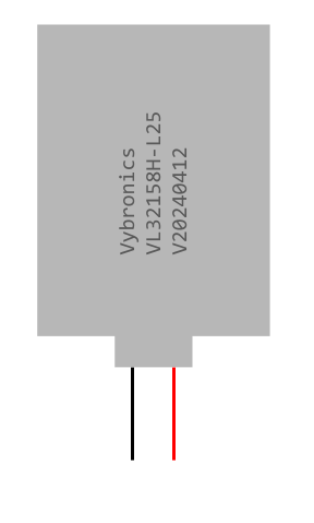
The Linear Resonant Actuator (LRA) Vibration Motor by Vybronics (Part ID: LRA) is a compact and efficient actuator designed to produce vibrations through the oscillation of a mass on a spring. Unlike traditional eccentric rotating mass (ERM) motors, LRAs operate at a specific resonant frequency, offering higher efficiency, faster response times, and more precise control. These features make LRAs ideal for applications requiring haptic feedback, such as mobile devices, wearables, gaming controllers, and medical devices.
Explore Projects Built with LRA Vibration Motor
 Open Project in Cirkit Designer
 Open Project in Cirkit Designer
 Open Project in Cirkit Designer
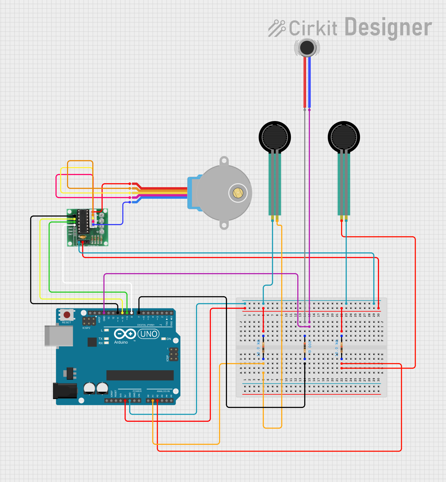 Open Project in Cirkit Designer
Explore Projects Built with LRA Vibration Motor
Open Project in Cirkit DesignerOpen Project in Cirkit DesignerOpen Project in Cirkit DesignerOpen Project in Cirkit DesignerCommon Applications:
- Haptic Feedback: Used in smartphones, tablets, and gaming controllers for tactile notifications.
- Wearable Devices: Provides discreet alerts in smartwatches and fitness trackers.
- Medical Devices: Enables tactile feedback in handheld diagnostic tools.
- Automotive Interfaces: Enhances user experience in touch-based control panels.
Technical Specifications
Key Technical Details:
| Parameter | Value |
|---|---|
| Manufacturer | Vybronics |
| Part ID | LRA |
| Operating Voltage Range | 2.0V to 3.6V |
| Nominal Voltage | 3.0V |
| Resonant Frequency | ~175 Hz |
| Typical Current Consumption | 80 mA (at 3.0V) |
| Maximum Vibration Amplitude | ~0.5 G |
| Dimensions | Varies by model (e.g., 10mm x 3mm) |
| Operating Temperature Range | -20°C to +70°C |
| Lifetime | >1,000,000 cycles |
Pin Configuration and Descriptions:
| Pin | Name | Description |
|---|---|---|
| 1 | V+ | Positive power supply (2.0V to 3.6V) |
| 2 | GND | Ground connection |
Usage Instructions
How to Use the LRA Vibration Motor in a Circuit:
- Power Supply: Connect the V+ pin to a regulated power source within the operating voltage range (2.0V to 3.6V). Ensure the GND pin is connected to the circuit ground.
- Driver Circuit: Use an LRA-specific driver IC (e.g., Texas Instruments DRV2605L) to drive the motor. These drivers are optimized for LRAs and provide features like automatic resonance tracking and haptic waveform generation.
- Control Signal: The driver IC can be controlled via I2C or PWM signals from a microcontroller (e.g., Arduino UNO) to generate desired vibration patterns.
- Mounting: Secure the LRA motor to the device chassis using adhesive or a mounting bracket to ensure efficient vibration transfer.
Important Considerations and Best Practices:
- Resonant Frequency: Always drive the LRA at its resonant frequency (~175 Hz) for optimal performance.
- Driver IC: Avoid directly connecting the LRA to a microcontroller GPIO pin. Use a dedicated driver IC to prevent damage and ensure proper operation.
- Power Supply: Use a stable power source to avoid fluctuations that could affect vibration performance.
- Thermal Management: Ensure adequate ventilation if the motor is used continuously at high power to prevent overheating.
- Testing: Test the motor in the final assembly to verify that vibrations are effectively transmitted to the user.
Example: Connecting the LRA to an Arduino UNO
Below is an example of how to control the LRA motor using an Arduino UNO and the DRV2605L driver IC.
Circuit Diagram:
- Connect the V+ pin of the LRA to the OUT+ pin of the DRV2605L.
- Connect the GND pin of the LRA to the OUT- pin of the DRV2605L.
- Connect the DRV2605L to the Arduino UNO via I2C (SDA and SCL pins).
Arduino Code:
#include <Wire.h>
#include <Adafruit_DRV2605.h>

// Initialize the DRV2605L driver
Adafruit_DRV2605 drv;

void setup() {
  Serial.begin(9600);
  Serial.println("Initializing DRV2605L...");

  // Begin communication with the DRV2605L
  if (!drv.begin()) {
    Serial.println("Failed to initialize DRV2605L. Check connections.");
    while (1);
  }
  Serial.println("DRV2605L initialized successfully.");

  // Select the haptic effect library
  drv.selectLibrary(1);

  // Set the effect to play (e.g., effect #1)
  drv.setMode(DRV2605_MODE_INTTRIG); // Internal trigger mode
  drv.setWaveform(0, 1);            // Play effect #1
  drv.setWaveform(1, 0);            // End of waveform sequence
}

void loop() {
  Serial.println("Activating LRA motor...");
  drv.go(); // Start the vibration effect
  delay(500); // Run the effect for 500ms

  Serial.println("Stopping LRA motor...");
  delay(1000); // Wait for 1 second before repeating
}
Troubleshooting and FAQs
Common Issues:
Motor Does Not Vibrate:
- Cause: Incorrect wiring or insufficient power supply.
- Solution: Verify all connections and ensure the power supply meets the motor's voltage and current requirements.
Weak Vibration:
- Cause: Driving the motor at a non-resonant frequency.
- Solution: Use a driver IC with automatic resonance tracking to ensure the motor operates at its resonant frequency.
Overheating:
- Cause: Prolonged operation at high power without proper ventilation.
- Solution: Reduce the duty cycle or provide adequate cooling.
Driver IC Not Detected:
- Cause: Incorrect I2C connections or address mismatch.
- Solution: Check the SDA and SCL connections and ensure the correct I2C address is used in the code.
FAQs:
Q: Can I drive the LRA motor directly from an Arduino GPIO pin?
A: No, LRAs require more current than a GPIO pin can provide. Always use a dedicated driver IC.Q: How do I select the right driver IC for my LRA motor?
A: Choose a driver IC designed for LRAs, such as the DRV2605L, which supports resonance tracking and haptic waveform generation.Q: Can I use the LRA motor in a battery-powered device?
A: Yes, LRAs are energy-efficient and suitable for battery-powered applications. Ensure the battery can supply sufficient current.Q: What is the lifespan of the LRA motor?
A: The Vybronics LRA motor has a lifespan of over 1,000,000 cycles under normal operating conditions.
This documentation provides a comprehensive guide to understanding, using, and troubleshooting the Vybronics LRA Vibration Motor. For further assistance, refer to the manufacturer's datasheet or contact technical support.