How to Use Diyuser 1.3 Oled SH1106: Examples, Pinouts, and Specs
Introduction
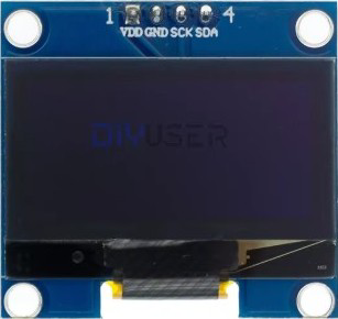
The Diyuser 1.3 Oled SH1106 is a 1.3-inch OLED display module manufactured by Arduino, featuring the SH1106 driver. This display is known for its high contrast, low power consumption, and wide viewing angles, making it an excellent choice for a variety of DIY electronics projects. It communicates via the I2C protocol, which simplifies wiring and integration with microcontrollers like the Arduino UNO.
Explore Projects Built with Diyuser 1.3 Oled SH1106

Explore Projects Built with Diyuser 1.3 Oled SH1106
Common Applications and Use Cases
- Displaying text, graphics, or sensor data in embedded systems
- DIY projects such as clocks, weather stations, and IoT devices
- Portable devices requiring low-power displays
- Debugging and monitoring microcontroller outputs
Technical Specifications
Key Technical Details
- Display Type: OLED (Organic Light Emitting Diode)
- Driver IC: SH1106
- Screen Size: 1.3 inches
- Resolution: 128 x 64 pixels
- Interface: I2C (Inter-Integrated Circuit)
- Operating Voltage: 3.3V to 5V
- Power Consumption: Low power, typically < 20mA
- Viewing Angle: > 160 degrees
- Dimensions: 35mm x 35mm x 4mm (approx.)
- Operating Temperature: -40°C to +85°C
Pin Configuration and Descriptions
The Diyuser 1.3 Oled SH1106 module has a 4-pin interface for I2C communication. Below is the pinout:
| Pin | Name | Description |
|---|---|---|
| 1 | GND | Ground pin. Connect to the ground of the circuit. |
| 2 | VCC | Power supply pin. Connect to 3.3V or 5V. |
| 3 | SCL | I2C clock line. Connect to the SCL pin of MCU. |
| 4 | SDA | I2C data line. Connect to the SDA pin of MCU. |
Usage Instructions
How to Use the Component in a Circuit
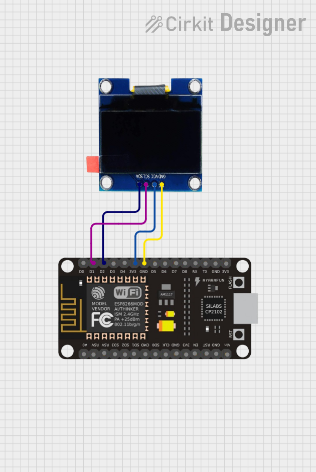
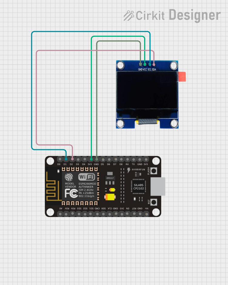
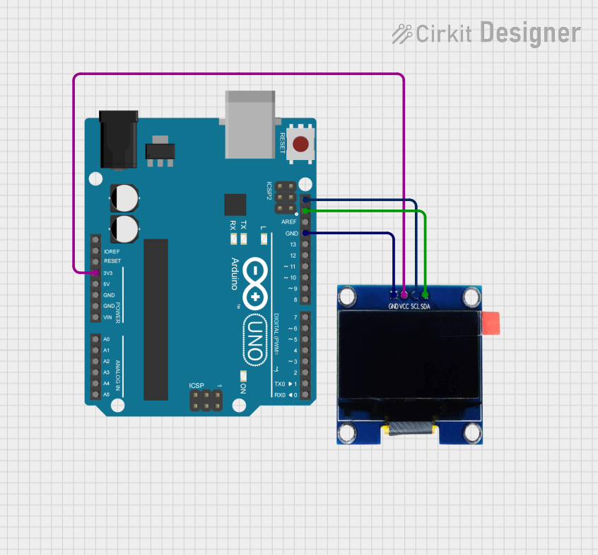
Wiring the Display:
- Connect the
GNDpin of the display to the ground (GND) of your microcontroller. - Connect the
VCCpin to a 3.3V or 5V power source, depending on your microcontroller's voltage. - Connect the
SCLpin to the I2C clock line (e.g., A5 on Arduino UNO). - Connect the
SDApin to the I2C data line (e.g., A4 on Arduino UNO).
- Connect the
Install Required Libraries:
- Use the Arduino IDE to install the
Adafruit_GFXandAdafruit_SH1106libraries. These libraries provide functions for controlling the SH1106 display.
- Use the Arduino IDE to install the
Upload Example Code:
- Below is a sample code snippet to display "Hello, World!" on the screen:
#include <Adafruit_GFX.h>       // Graphics library for OLED
#include <Adafruit_SH1106.h>    // SH1106 driver library

#define OLED_RESET -1           // Reset pin not used
Adafruit_SH1106 display(OLED_RESET);

void setup() {
  display.begin(SH1106_I2C_ADDRESS, 0x3C); // Initialize display with I2C address
  display.clearDisplay();                 // Clear the display buffer
  display.setTextSize(1);                 // Set text size to 1 (smallest)
  display.setTextColor(WHITE);            // Set text color to white
  display.setCursor(0, 0);                // Set cursor to top-left corner
  display.println("Hello, World!");       // Print text to display buffer
  display.display();                      // Send buffer to display
}

void loop() {
  // Nothing to do here
}
Important Considerations and Best Practices
- Ensure the I2C address of the display matches the one in your code. The default address is
0x3C. - Use pull-up resistors (typically 4.7kΩ) on the
SCLandSDAlines if your microcontroller does not have internal pull-ups. - Avoid exposing the display to voltages higher than 5V to prevent damage.
- Handle the module carefully to avoid damaging the OLED screen.
Troubleshooting and FAQs
Common Issues and Solutions
Display Not Turning On:
- Verify the wiring connections, especially
GNDandVCC. - Ensure the power supply voltage is within the specified range (3.3V to 5V).
- Verify the wiring connections, especially
No Output on the Screen:
- Check the I2C address in the code. Use an I2C scanner sketch to confirm the address.
- Ensure the
Adafruit_GFXandAdafruit_SH1106libraries are correctly installed.
Flickering or Unstable Display:
- Add decoupling capacitors (e.g., 0.1µF) near the power pins to stabilize the voltage.
- Check for loose connections or poor soldering.
Text or Graphics Not Displaying Properly:
- Ensure the correct resolution (128x64) is set in the library or code.
- Clear the display buffer (
display.clearDisplay()) before updating the screen.
FAQs
Q: Can I use this display with a 3.3V microcontroller like ESP32?
A: Yes, the display is compatible with both 3.3V and 5V systems.
Q: What is the maximum cable length for I2C communication?
A: The I2C protocol is designed for short distances, typically less than 1 meter. For longer distances, use lower clock speeds or I2C extenders.
Q: Can I use this display with SPI instead of I2C?
A: No, this module is designed specifically for I2C communication.
Q: How do I display custom graphics?
A: Use the Adafruit_GFX library to draw shapes, bitmaps, or custom graphics. Refer to the library documentation for examples.
By following this documentation, you can effectively integrate the Diyuser 1.3 Oled SH1106 into your projects and troubleshoot common issues.