Cirkit Designer Logo
Cirkit Designer
Your all-in-one circuit design IDE
Home / 
Component Documentation

How to Use SDcardHeaders: Examples, Pinouts, and Specs

Image of SDcardHeaders
Cirkit Designer LogoDesign with SDcardHeaders in Cirkit Designer

Introduction

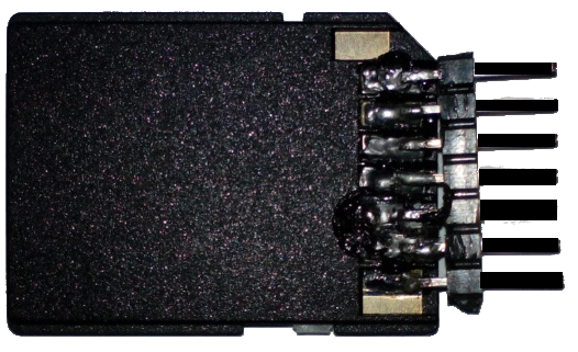
SD card headers are integral components in modern electronics, providing a standardized interface for Secure Digital (SD) memory cards. These connectors allow for the easy insertion and removal of SD cards, which are widely used for portable storage in devices such as digital cameras, smartphones, laptops, and embedded systems like the Arduino UNO. SD card headers are designed to accommodate the physical and electrical interface of SD cards, enabling data transfer between the card and the host device.

Explore Projects Built with SDcardHeaders

Use Cirkit Designer to design, explore, and prototype these projects online. Some projects support real-time simulation. Click "Open Project" to start designing instantly!
Arduino UNO SD Card Data Logger
Image of sd card: A project utilizing SDcardHeaders in a practical application
This circuit consists of an Arduino UNO connected to an SD card module. The Arduino provides power and ground to the SD module and interfaces with it using SPI communication through digital pins D10 (CS), D11 (MOSI), D12 (MISO), and D13 (SCK). The setup is intended for reading from or writing to an SD card using the Arduino.
Cirkit Designer LogoOpen Project in Cirkit Designer
ESP32-C3 and Micro SD Card Module for Data Logging
Image of Esp 32 super mini with MicroSd module: A project utilizing SDcardHeaders in a practical application
This circuit features an ESP32-C3 microcontroller interfaced with a Micro SD Card Module. The ESP32-C3 handles SPI communication with the SD card for data storage and retrieval, with specific GPIO pins assigned for MOSI, MISO, SCK, and CS signals.
Cirkit Designer LogoOpen Project in Cirkit Designer
Arduino UNO R4 WiFi Controlled Data Logger with BNO055 Sensor and Micro SD Storage
Image of Main Telemetry R4: A project utilizing SDcardHeaders in a practical application
This circuit features an Arduino UNO R4 WiFi microcontroller connected to a Micro SD Card Module for data storage, a BNO055 sensor for orientation data, and three red LEDs for indication purposes. The LEDs are controlled by digital pins D2, D3, and D4, and can be turned on or off using a single-pole single-throw (SPST) toggle switch connected to their common cathodes and ground. The BNO055 sensor interfaces with the Arduino via I2C communication using the SDA and SCL pins, and the Micro SD Card Module is interfaced using SPI with chip select on pin D10 and data lines on pins D11 (MOSI), D12 (MISO), and D13 (SCK).
Cirkit Designer LogoOpen Project in Cirkit Designer
ESP32-Based SD Card Data Logger
Image of Data Logging: A project utilizing SDcardHeaders in a practical application
This circuit connects an ESP32 Wroom Dev Kit microcontroller to a Micro SD Card Module for data storage purposes. The ESP32 is configured to communicate with the SD card using the SPI protocol, as indicated by the connections of MOSI, MISO, SCK, and CS pins. A separate Vcc component provides power to the SD card module.
Cirkit Designer LogoOpen Project in Cirkit Designer

Explore Projects Built with SDcardHeaders

Use Cirkit Designer to design, explore, and prototype these projects online. Some projects support real-time simulation. Click "Open Project" to start designing instantly!
Image of sd card: A project utilizing SDcardHeaders in a practical application
Arduino UNO SD Card Data Logger
This circuit consists of an Arduino UNO connected to an SD card module. The Arduino provides power and ground to the SD module and interfaces with it using SPI communication through digital pins D10 (CS), D11 (MOSI), D12 (MISO), and D13 (SCK). The setup is intended for reading from or writing to an SD card using the Arduino.
Cirkit Designer LogoOpen Project in Cirkit Designer
Image of Esp 32 super mini with MicroSd module: A project utilizing SDcardHeaders in a practical application
ESP32-C3 and Micro SD Card Module for Data Logging
This circuit features an ESP32-C3 microcontroller interfaced with a Micro SD Card Module. The ESP32-C3 handles SPI communication with the SD card for data storage and retrieval, with specific GPIO pins assigned for MOSI, MISO, SCK, and CS signals.
Cirkit Designer LogoOpen Project in Cirkit Designer
Image of Main Telemetry R4: A project utilizing SDcardHeaders in a practical application
Arduino UNO R4 WiFi Controlled Data Logger with BNO055 Sensor and Micro SD Storage
This circuit features an Arduino UNO R4 WiFi microcontroller connected to a Micro SD Card Module for data storage, a BNO055 sensor for orientation data, and three red LEDs for indication purposes. The LEDs are controlled by digital pins D2, D3, and D4, and can be turned on or off using a single-pole single-throw (SPST) toggle switch connected to their common cathodes and ground. The BNO055 sensor interfaces with the Arduino via I2C communication using the SDA and SCL pins, and the Micro SD Card Module is interfaced using SPI with chip select on pin D10 and data lines on pins D11 (MOSI), D12 (MISO), and D13 (SCK).
Cirkit Designer LogoOpen Project in Cirkit Designer
Image of Data Logging: A project utilizing SDcardHeaders in a practical application
ESP32-Based SD Card Data Logger
This circuit connects an ESP32 Wroom Dev Kit microcontroller to a Micro SD Card Module for data storage purposes. The ESP32 is configured to communicate with the SD card using the SPI protocol, as indicated by the connections of MOSI, MISO, SCK, and CS pins. A separate Vcc component provides power to the SD card module.
Cirkit Designer LogoOpen Project in Cirkit Designer

Technical Specifications

General Characteristics

  • Type: Push-Push, Push-Pull, or Hinge type
  • Number of Contacts: Typically 9 for standard SD cards
  • Mounting Type: Surface mount or through-hole
  • Card Detection: With or without card detection switch
  • Durability: Rated for a certain number of card insertion/removal cycles
  • Operating Temperature Range: Specified by manufacturer

Electrical Specifications

  • Rated Voltage: 3.3V typical for SD interface
  • Rated Current: Varies with manufacturer and model
  • Contact Resistance: Specified by manufacturer
  • Insulation Resistance: Specified by manufacturer
  • Dielectric Withstanding Voltage: Specified by manufacturer

Pin Configuration and Descriptions

Pin Number Name Description
1 DAT2/NC Data line 2 (Not connected in SPI mode)
2 CD/DAT3 Card Detect/Data line 3
3 CMD Command/Response line
4 VDD Supply Voltage (3.3V)
5 CLK Clock
6 VSS Ground
7 DAT0 Data line 0
8 DAT1 Data line 1
9 DAT2/NC Data line 2 (Not connected in SPI mode)

Usage Instructions

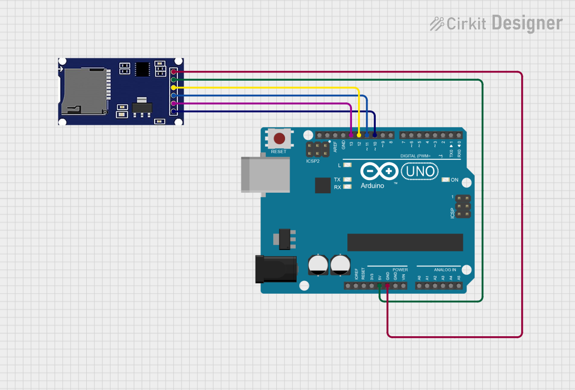
Integration into a Circuit

  1. Mounting: Secure the SD card header onto the PCB, ensuring proper alignment and soldering for electrical connectivity.
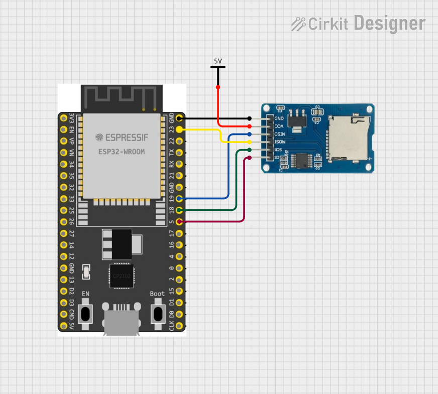
  2. Power Supply: Connect the VDD pin to a 3.3V power supply and VSS to ground.
  3. Data Lines: Connect the CMD, DAT0, DAT1, DAT2, and DAT3 lines to the corresponding host interface.
  4. Clock: Connect the CLK pin to the clock signal from the host device.
  5. Card Detection: If available, connect the CD/DAT3 pin to the host device for card detection functionality.

Best Practices

  • Use ESD precautions when handling the SD card header to prevent damage.
  • Ensure that the power supply is stable and clean to avoid data corruption.
  • Implement proper pull-up/pull-down resistors on the data lines as required by the SD card specifications.
  • Provide adequate strain relief to prevent mechanical stress on the SD card header.

Example Code for Arduino UNO

#include <SPI.h>
#include <SD.h>

// SD card chip select pin
const int chipSelect = 10;

void setup() {
  // Open serial communications
  Serial.begin(9600);
  
  // Initialize the SD card
  if (!SD.begin(chipSelect)) {
    Serial.println("Initialization failed!");
    return;
  }
  Serial.println("Initialization done.");
}

void loop() {
  // Code to read or write data to/from the SD card
}

Troubleshooting and FAQs

Common Issues

  • SD Card Not Recognized: Ensure the card is inserted correctly and the pins are properly aligned.
  • Read/Write Errors: Check for loose connections and verify that the power supply is stable.
  • Corrupted Data: Use high-quality SD cards and ensure proper power-down sequences.

FAQs

Q: Can I use a 5V power supply with the SD card header? A: No, SD cards typically operate at 3.3V. Using a 5V supply can damage the card and the header.

Q: How do I know if the SD card is inserted properly? A: Some SD card headers have a card detection switch that can be used to detect the presence of a card.

Q: What is the maximum storage capacity supported by SD card headers? A: The storage capacity is determined by the SD card itself, not the header. However, the host device must support the SD card's format (e.g., SDHC, SDXC).

Q: Can I hot-swap SD cards using the SD card header? A: While some headers are designed for hot-swapping, it is generally recommended to power down the host device before changing cards to prevent data loss or corruption.