Cirkit Designer Logo
Cirkit Designer
Your all-in-one circuit design IDE
Home / 
Component Documentation

How to Use MAX7219 8 Digit 7 Segment: Examples, Pinouts, and Specs

Image of MAX7219 8 Digit 7 Segment
Cirkit Designer LogoDesign with MAX7219 8 Digit 7 Segment in Cirkit Designer

Introduction

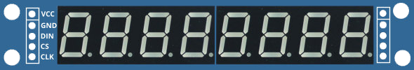
The MAX7219 from Maxim Integrated is a compact, serial input/output common-cathode display driver that can interface microcontrollers to 7-segment numeric LED displays of up to 8 digits. Its primary function is to convert a serial input to parallel outputs for LED display. It is widely used in applications such as digital clocks, electronic meters, and other devices that require numeric displays.

Explore Projects Built with MAX7219 8 Digit 7 Segment

Use Cirkit Designer to design, explore, and prototype these projects online. Some projects support real-time simulation. Click "Open Project" to start designing instantly!
Teensy 4.0 and MAX7219-Based 7-Segment Display Counter
Image of dispay: A project utilizing MAX7219 8 Digit 7 Segment in a practical application
This circuit uses a Teensy 4.0 microcontroller to control a MAX7219 LED driver, which in turn drives three 7-segment displays. The microcontroller runs code to display numbers from 0 to 999 on the 7-segment displays, with the SN74AHCT125N buffer providing signal integrity and the necessary capacitors and resistors ensuring stable operation.
Cirkit Designer LogoOpen Project in Cirkit Designer
Arduino UNO Controlled Seven-Segment Display Counter
Image of Arduino Uno - Seven Segment Display (Sim-C): A project utilizing MAX7219 8 Digit 7 Segment in a practical application
This circuit uses an Arduino UNO to control a seven-segment display, displaying digits from 0 to 9 with a one-second delay between each digit. The Arduino drives the segments of the common anode display by setting the corresponding pins to LOW, as defined in the provided sketch code.
Cirkit Designer LogoOpen Project in Cirkit Designer
Arduino UNO 4-Digit 7-Segment Display Counter
Image of arduino: A project utilizing MAX7219 8 Digit 7 Segment in a practical application
This circuit uses an Arduino UNO to control a 4-digit 7-segment display. The Arduino is programmed to sequentially display the numbers 1, 2, 3, and 4 on the display by driving the appropriate segments and digits.
Cirkit Designer LogoOpen Project in Cirkit Designer
Arduino UNO 4-Digit Seven Segment Display Counter
Image of 4 Digit Seven Segment Display (SIM-C): A project utilizing MAX7219 8 Digit 7 Segment in a practical application
This circuit uses an Arduino UNO to control a 4-digit seven-segment display. The Arduino runs a program that counts up in deci-seconds and displays the count on the seven-segment display using the SevSeg library.
Cirkit Designer LogoOpen Project in Cirkit Designer

Explore Projects Built with MAX7219 8 Digit 7 Segment

Use Cirkit Designer to design, explore, and prototype these projects online. Some projects support real-time simulation. Click "Open Project" to start designing instantly!
Image of dispay: A project utilizing MAX7219 8 Digit 7 Segment in a practical application
Teensy 4.0 and MAX7219-Based 7-Segment Display Counter
This circuit uses a Teensy 4.0 microcontroller to control a MAX7219 LED driver, which in turn drives three 7-segment displays. The microcontroller runs code to display numbers from 0 to 999 on the 7-segment displays, with the SN74AHCT125N buffer providing signal integrity and the necessary capacitors and resistors ensuring stable operation.
Cirkit Designer LogoOpen Project in Cirkit Designer
Image of Arduino Uno - Seven Segment Display (Sim-C): A project utilizing MAX7219 8 Digit 7 Segment in a practical application
Arduino UNO Controlled Seven-Segment Display Counter
This circuit uses an Arduino UNO to control a seven-segment display, displaying digits from 0 to 9 with a one-second delay between each digit. The Arduino drives the segments of the common anode display by setting the corresponding pins to LOW, as defined in the provided sketch code.
Cirkit Designer LogoOpen Project in Cirkit Designer
Image of arduino: A project utilizing MAX7219 8 Digit 7 Segment in a practical application
Arduino UNO 4-Digit 7-Segment Display Counter
This circuit uses an Arduino UNO to control a 4-digit 7-segment display. The Arduino is programmed to sequentially display the numbers 1, 2, 3, and 4 on the display by driving the appropriate segments and digits.
Cirkit Designer LogoOpen Project in Cirkit Designer
Image of 4 Digit Seven Segment Display (SIM-C): A project utilizing MAX7219 8 Digit 7 Segment in a practical application
Arduino UNO 4-Digit Seven Segment Display Counter
This circuit uses an Arduino UNO to control a 4-digit seven-segment display. The Arduino runs a program that counts up in deci-seconds and displays the count on the seven-segment display using the SevSeg library.
Cirkit Designer LogoOpen Project in Cirkit Designer

Technical Specifications

Key Features

  • 10MHz Serial Interface
  • Individual LED segment control
  • Drive common-cathode LED display up to 8 digits
  • 150μA low-power shutdown (data retained)
  • Digital brightness control
  • Display-blanked on power-up
  • Drive 7-segment digits and/or discrete LEDs

Electrical Characteristics

  • Supply Voltage (V): +4.0V to +5.5V
  • Supply Current (I): 330μA
  • Operating Temperature Range: -40°C to +85°C

Pin Configuration and Descriptions

Pin Number Name Description
1 DIN Serial-Data Input
2 CS Chip Select (active low)
3 CLK Serial-Clock Input
4 GND Ground
5 DOUT Serial-Data Output
6 LOAD Load Data into Display Register
7-14 DIG0-DIG7 Digit Drive Lines (active low)
15-22 SEG A-G, DP Segment Drive Lines (active high)
23 ISET Set Current
24 V+ Positive Supply Voltage

Usage Instructions

Interfacing with a Microcontroller

  1. Connect V+ and GND to the power supply (4.0V to 5.5V).
  2. Connect DIN, CS, and CLK to the microcontroller's SPI pins.
  3. Connect ISET to a resistor to set the segment current.
  4. Connect the DIG and SEG pins to the 7-segment display.

Programming the MAX7219

To control the MAX7219, send data serially using the SPI protocol. The data consists of a 4-bit register address and an 8-bit data byte.

Example Arduino Code

#include <SPI.h>

// Define the connections to the MAX7219
#define CS_PIN  10

void setup() {
  // Set the CS pin as an output
  pinMode(CS_PIN, OUTPUT);
  // Begin SPI
  SPI.begin();
  // Initialize the MAX7219
  max7219Init();
}

void loop() {
  // Update display with some value
  max7219DisplayNumber(12345678);
}

void max7219Init() {
  // Set the number of digits to use
  max7219SendData(0x0B, 0x07);
  // Use normal operation mode
  max7219SendData(0x0C, 0x01);
  // Set the intensity (brightness) of the display
  max7219SendData(0x0A, 0x08);
  // No decode for the digits
  max7219SendData(0x09, 0x00);
}

void max7219SendData(byte registerAddress, byte data) {
  // Enable the CS pin
  digitalWrite(CS_PIN, LOW);
  // Send the register address
  SPI.transfer(registerAddress);
  // Send the data
  SPI.transfer(data);
  // Disable the CS pin
  digitalWrite(CS_PIN, HIGH);
}

void max7219DisplayNumber(long number) {
  // Display each digit of the number
  for (int i = 0; i < 8; i++) {
    byte digit = number % 10;
    max7219SendData(i + 1, digit);
    number /= 10;
  }
}

Best Practices

  • Use a current-limiting resistor with ISET to prevent damage to the LEDs.
  • Ensure that the power supply voltage is within the specified range.
  • Avoid sending data to the MAX7219 while the display is being updated to prevent flickering.

Troubleshooting and FAQs

Common Issues

  • Display not lighting up: Check the power supply connections and the current-limiting resistor on ISET.
  • Garbled display: Ensure that the SPI data is being sent correctly and that there is no noise on the communication lines.
  • Dim display: Adjust the brightness control register or check the current-limiting resistor.

FAQs

Q: Can the MAX7219 drive other types of LEDs? A: Yes, it can drive discrete LEDs in addition to 7-segment displays.

Q: How do I control the brightness of the display? A: Use the intensity register (0x0A) to adjust the brightness level.

Q: Can I daisy-chain multiple MAX7219s? A: Yes, you can connect the DOUT of one MAX7219 to the DIN of the next and control multiple devices with a single microcontroller.

For further assistance, consult the MAX7219 datasheet provided by Maxim Integrated.