Cirkit Designer Logo
Cirkit Designer
Your all-in-one circuit design IDE
Home / 
Component Documentation

How to Use HW-504 Joystick: Examples, Pinouts, and Specs

Image of HW-504 Joystick
Cirkit Designer LogoDesign with HW-504 Joystick in Cirkit Designer

Introduction

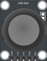
The HW-504 Joystick is a versatile input device designed for controlling movement in a wide range of applications. It features dual-axis motion (X and Y axes) and is often equipped with a push-button for additional functionality. This joystick is commonly used in robotics, gaming controllers, remote-controlled vehicles, and other interactive systems requiring precise directional input.

Its compact design and ease of integration make it a popular choice for hobbyists and professionals alike. The HW-504 Joystick is compatible with microcontrollers such as Arduino, Raspberry Pi, and other development boards, making it an excellent choice for prototyping and DIY projects.

Explore Projects Built with HW-504 Joystick

Use Cirkit Designer to design, explore, and prototype these projects online. Some projects support real-time simulation. Click "Open Project" to start designing instantly!
Arduino Nano Joystick-Controlled Bluetooth Module with Battery Power
Image of padelpro transmitter: A project utilizing HW-504 Joystick in a practical application
This circuit is a wireless joystick controller that uses an Arduino Nano to read analog signals from a KY-023 Dual Axis Joystick Module and transmits the data via an HC-05 Bluetooth Module. The system is powered by a 18650 Li-Ion battery with a rocker switch for power control.
Cirkit Designer LogoOpen Project in Cirkit Designer
Arduino UNO Controlled Dual Servo Joystick Interface
Image of maze 2 game: A project utilizing HW-504 Joystick in a practical application
This circuit features an Arduino UNO microcontroller connected to two servo motors and a KY-023 dual-axis joystick module. The joystick provides two analog inputs to control the position of the servos, with the potential for a button input from the joystick as well. The servos are powered by the Arduino's 5V output, and their movement is controlled by PWM signals from the Arduino's digital pins.
Cirkit Designer LogoOpen Project in Cirkit Designer
Arduino UNO R4 WiFi Joystick-Controlled LED Matrix with Wi-Fi Connectivity
Image of joystick: A project utilizing HW-504 Joystick in a practical application
This circuit features an Arduino UNO R4 WiFi microcontroller interfaced with a KY-023 Dual Axis Joystick Module and three pushbuttons, each connected through a 200-ohm resistor. The Arduino reads the joystick and button states, processes the data, and sends it via WiFi UDP to a specified host, while also controlling an LED matrix for visual feedback.
Cirkit Designer LogoOpen Project in Cirkit Designer
Wireless Joystick-Controlled Interface with Arduino Nano and NRF24L01
Image of Transmitter 11: A project utilizing HW-504 Joystick in a practical application
This circuit features an Arduino Nano interfaced with a KY-023 Dual Axis Joystick Module for analog input, and an NRF24L01 module for wireless communication. The joystick provides x and y-axis control signals to the Arduino's analog inputs and a switch signal to a digital input, while the NRF24L01 enables the Arduino to communicate with other devices wirelessly. The 2x 18650 batteries supply power to the Arduino, which in turn powers the joystick and the NRF24L01 module.
Cirkit Designer LogoOpen Project in Cirkit Designer

Explore Projects Built with HW-504 Joystick

Use Cirkit Designer to design, explore, and prototype these projects online. Some projects support real-time simulation. Click "Open Project" to start designing instantly!
Image of padelpro transmitter: A project utilizing HW-504 Joystick in a practical application
Arduino Nano Joystick-Controlled Bluetooth Module with Battery Power
This circuit is a wireless joystick controller that uses an Arduino Nano to read analog signals from a KY-023 Dual Axis Joystick Module and transmits the data via an HC-05 Bluetooth Module. The system is powered by a 18650 Li-Ion battery with a rocker switch for power control.
Cirkit Designer LogoOpen Project in Cirkit Designer
Image of maze 2 game: A project utilizing HW-504 Joystick in a practical application
Arduino UNO Controlled Dual Servo Joystick Interface
This circuit features an Arduino UNO microcontroller connected to two servo motors and a KY-023 dual-axis joystick module. The joystick provides two analog inputs to control the position of the servos, with the potential for a button input from the joystick as well. The servos are powered by the Arduino's 5V output, and their movement is controlled by PWM signals from the Arduino's digital pins.
Cirkit Designer LogoOpen Project in Cirkit Designer
Image of joystick: A project utilizing HW-504 Joystick in a practical application
Arduino UNO R4 WiFi Joystick-Controlled LED Matrix with Wi-Fi Connectivity
This circuit features an Arduino UNO R4 WiFi microcontroller interfaced with a KY-023 Dual Axis Joystick Module and three pushbuttons, each connected through a 200-ohm resistor. The Arduino reads the joystick and button states, processes the data, and sends it via WiFi UDP to a specified host, while also controlling an LED matrix for visual feedback.
Cirkit Designer LogoOpen Project in Cirkit Designer
Image of Transmitter 11: A project utilizing HW-504 Joystick in a practical application
Wireless Joystick-Controlled Interface with Arduino Nano and NRF24L01
This circuit features an Arduino Nano interfaced with a KY-023 Dual Axis Joystick Module for analog input, and an NRF24L01 module for wireless communication. The joystick provides x and y-axis control signals to the Arduino's analog inputs and a switch signal to a digital input, while the NRF24L01 enables the Arduino to communicate with other devices wirelessly. The 2x 18650 batteries supply power to the Arduino, which in turn powers the joystick and the NRF24L01 module.
Cirkit Designer LogoOpen Project in Cirkit Designer

Technical Specifications

  • Model: HW-504 Joystick
  • Operating Voltage: 3.3V to 5V
  • Output Type: Analog (X and Y axes), Digital (push-button)
  • X and Y Axis Range: 0V to Vcc (typically 0V to 5V)
  • Push-Button Output: Active LOW
  • Dimensions: 40mm x 26mm x 32mm (approx.)
  • Mounting Holes: M2 screws

Pin Configuration and Descriptions

The HW-504 Joystick typically has 5 pins. The table below describes each pin:

Pin Label Description
1 GND Ground connection
2 +5V Power supply (3.3V to 5V)
3 VRx Analog output for X-axis movement
4 VRy Analog output for Y-axis movement
5 SW Digital output for push-button (Active LOW)

Usage Instructions

How to Use the HW-504 Joystick in a Circuit

  1. Power the Joystick: Connect the +5V pin to the 5V output of your microcontroller and the GND pin to ground.
  2. Read Analog Outputs: Connect the VRx and VRy pins to the analog input pins of your microcontroller to read the X and Y axis values.
  3. Read the Push-Button: Connect the SW pin to a digital input pin of your microcontroller. Use a pull-up resistor if necessary, as the button output is active LOW.
  4. Calibrate the Joystick: The joystick outputs a voltage range corresponding to its position. The center position typically outputs a voltage near half of the supply voltage (e.g., ~2.5V for a 5V supply). Ensure your code accounts for this.

Important Considerations and Best Practices

  • Debouncing the Button: When using the push-button, implement software debouncing to avoid false triggers.
  • Voltage Compatibility: Ensure the joystick's operating voltage matches your microcontroller's input voltage range.
  • Mechanical Limits: Avoid applying excessive force to the joystick to prevent damage.
  • Noise Filtering: Use capacitors on the analog output lines if you experience noisy readings.

Example Code for Arduino UNO

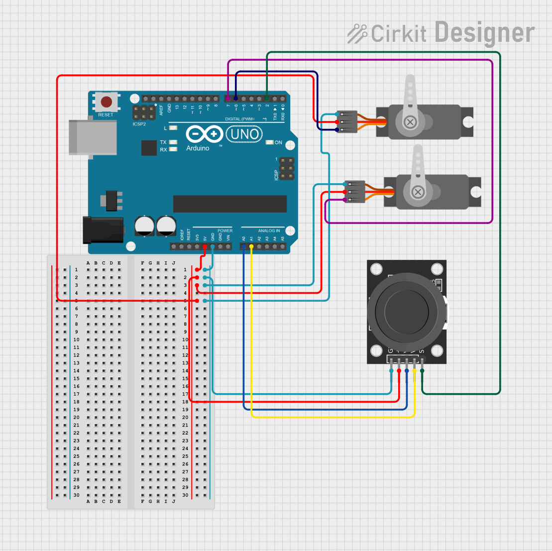
Below is an example of how to interface the HW-504 Joystick with an Arduino UNO:

// Define pin connections
const int VRxPin = A0; // X-axis connected to analog pin A0
const int VRyPin = A1; // Y-axis connected to analog pin A1
const int SWPin = 2;   // Push-button connected to digital pin 2

void setup() {
  // Initialize serial communication for debugging
  Serial.begin(9600);

  // Configure the push-button pin as input with internal pull-up resistor
  pinMode(SWPin, INPUT_PULLUP);
}

void loop() {
  // Read the X and Y axis values (0 to 1023 for 10-bit ADC)
  int xValue = analogRead(VRxPin);
  int yValue = analogRead(VRyPin);

  // Read the push-button state (LOW when pressed)
  bool buttonState = digitalRead(SWPin) == LOW;

  // Print the joystick values to the Serial Monitor
  Serial.print("X: ");
  Serial.print(xValue);
  Serial.print(" | Y: ");
  Serial.print(yValue);
  Serial.print(" | Button: ");
  Serial.println(buttonState ? "Pressed" : "Released");

  // Add a small delay for stability
  delay(100);
}

Troubleshooting and FAQs

Common Issues

  1. No Output or Incorrect Readings:

    • Cause: Loose or incorrect wiring.
    • Solution: Double-check all connections and ensure the joystick is powered correctly.
  2. Push-Button Not Responding:

    • Cause: Missing pull-up resistor or incorrect pin configuration.
    • Solution: Use the INPUT_PULLUP mode in your code or add an external pull-up resistor.
  3. Noisy Analog Readings:

    • Cause: Electrical noise or interference.
    • Solution: Add decoupling capacitors (e.g., 0.1µF) between the analog output pins and ground.
  4. Joystick Not Centered:

    • Cause: Manufacturing tolerances or wear and tear.
    • Solution: Calibrate the joystick in software by determining the center values.

FAQs

Q1: Can I use the HW-504 Joystick with a 3.3V microcontroller?
A1: Yes, the joystick operates at 3.3V to 5V. Ensure the microcontroller's ADC can read the voltage range.

Q2: How do I extend the joystick's lifespan?
A2: Avoid applying excessive force or rapid, repetitive movements. Store the joystick in a dry, dust-free environment.

Q3: Can I use the joystick for PWM motor control?
A3: Yes, you can map the analog output values to PWM signals to control motor speed and direction.

Q4: What is the resolution of the joystick's analog output?
A4: The resolution depends on the microcontroller's ADC. For example, an Arduino UNO has a 10-bit ADC, providing values from 0 to 1023.