Cirkit Designer
Your all-in-one circuit design IDE
Home /
Component Documentation
How to Use Mosfet N: Examples, Pinouts, and Specs
Introduction
The MOSFET (Metal-Oxide-Semiconductor Field-Effect Transistor) N-Channel is a type of transistor used for switching and amplifying electronic signals. It operates by controlling the voltage and current between the source and drain terminals, with the gate terminal serving as the control input. N-Channel MOSFETs are widely used in various applications due to their efficiency and high-speed switching capabilities.
Explore Projects Built with Mosfet N
STM32 Nucleo-Controlled Solenoid Actuation System

This circuit appears to be a microcontroller-driven array of push-pull solenoids with flyback diodes for protection. The STM32 Nucleo F303RE microcontroller's GPIO pins are connected to the gates of several nMOS transistors, which act as switches to control the current flow to the solenoids. A pushbutton with a pull-up resistor is also interfaced with the microcontroller for user input, and the power supply is connected to the solenoids with ground return paths through the nMOS transistors.
Arduino UNO Controlled nMOS Transistor Array with Resistor Network
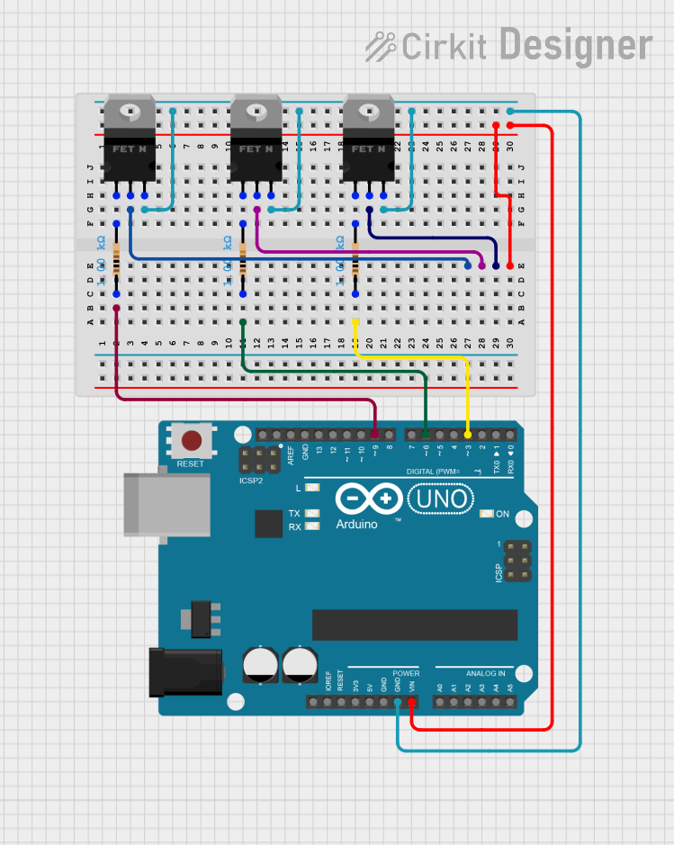
This circuit uses an Arduino UNO to control three nMOS transistors via three 1k Ohm resistors connected to digital pins D3, D6, and D9. The transistors' sources are tied to ground, and their gates are driven by the Arduino to switch the transistors on and off, likely for controlling high-power loads or other devices.
ESP32-Controlled Motor with IRFZ44N MOSFET
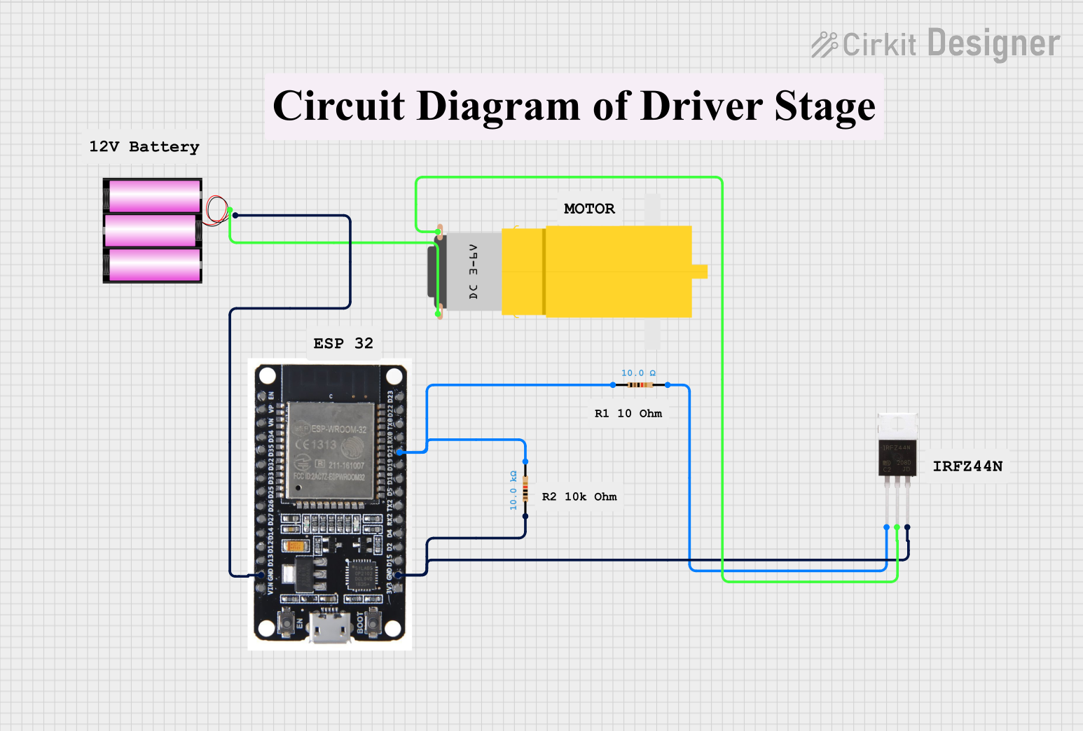
This circuit uses an ESP32 microcontroller to control a motor through an IRFZ44N MOSFET. The ESP32's GPIO pin D21 is connected through a 10-ohm resistor to the gate of the MOSFET, which switches the motor on and off. A 10k-ohm pull-down resistor is connected to the gate to ensure the MOSFET turns off when the GPIO pin is not driving it, and the motor is powered by a 12V battery.
Battery-Powered Fan Controller with NTC Thermistor and IRFZ44N MOSFET
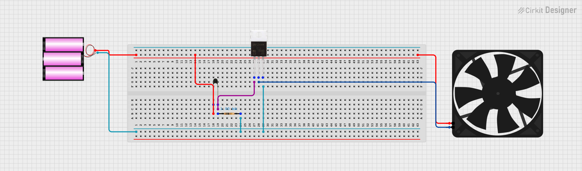
This circuit is a temperature-controlled fan system. It uses an NTC thermistor to sense temperature changes, which then modulates the gate of an IRFZ44N MOSFET through a resistor. The MOSFET controls the power to a fan, turning it on or off based on the temperature, with power supplied by a 12V battery.
Explore Projects Built with Mosfet N
STM32 Nucleo-Controlled Solenoid Actuation System
This circuit appears to be a microcontroller-driven array of push-pull solenoids with flyback diodes for protection. The STM32 Nucleo F303RE microcontroller's GPIO pins are connected to the gates of several nMOS transistors, which act as switches to control the current flow to the solenoids. A pushbutton with a pull-up resistor is also interfaced with the microcontroller for user input, and the power supply is connected to the solenoids with ground return paths through the nMOS transistors.
Arduino UNO Controlled nMOS Transistor Array with Resistor Network
This circuit uses an Arduino UNO to control three nMOS transistors via three 1k Ohm resistors connected to digital pins D3, D6, and D9. The transistors' sources are tied to ground, and their gates are driven by the Arduino to switch the transistors on and off, likely for controlling high-power loads or other devices.
ESP32-Controlled Motor with IRFZ44N MOSFET
This circuit uses an ESP32 microcontroller to control a motor through an IRFZ44N MOSFET. The ESP32's GPIO pin D21 is connected through a 10-ohm resistor to the gate of the MOSFET, which switches the motor on and off. A 10k-ohm pull-down resistor is connected to the gate to ensure the MOSFET turns off when the GPIO pin is not driving it, and the motor is powered by a 12V battery.
Battery-Powered Fan Controller with NTC Thermistor and IRFZ44N MOSFET
This circuit is a temperature-controlled fan system. It uses an NTC thermistor to sense temperature changes, which then modulates the gate of an IRFZ44N MOSFET through a resistor. The MOSFET controls the power to a fan, turning it on or off based on the temperature, with power supplied by a 12V battery.
Common Applications and Use Cases
- Power Supplies: Used in DC-DC converters and power management circuits.
- Motor Control: Employed in H-bridge circuits for controlling motors.
- Signal Amplification: Utilized in audio and RF amplifiers.
- Switching Circuits: Commonly used in digital and analog switching applications.
Technical Specifications
Key Technical Details
| Parameter | Value |
|---|---|
| Drain-Source Voltage (VDS) | 60V |
| Gate-Source Voltage (VGS) | ±20V |
| Continuous Drain Current (ID) | 30A |
| Power Dissipation (PD) | 150W |
| RDS(on) (Max) | 0.035Ω |
| Gate Threshold Voltage (VGS(th)) | 2-4V |
| Operating Temperature Range | -55°C to +150°C |
Pin Configuration and Descriptions
| Pin Number | Pin Name | Description |
|---|---|---|
| 1 | Gate | Controls the MOSFET switching |
| 2 | Drain | Current flows from drain to source |
| 3 | Source | Current flows to the drain |
| 4 | Substrate | Connected to the source internally |
Usage Instructions
How to Use the Component in a Circuit
- Identify the Pins: Ensure you correctly identify the gate, drain, and source pins.
- Connect the Gate: Connect the gate to the control signal. Use a resistor (typically 10Ω) to limit the gate current.
- Connect the Drain: Connect the drain to the load (e.g., motor, LED).
- Connect the Source: Connect the source to the ground or the negative terminal of the power supply.
- Power Supply: Ensure the power supply voltage does not exceed the maximum VDS rating.
Important Considerations and Best Practices
- Gate Drive Voltage: Ensure the gate drive voltage is within the specified range (typically 10V for full enhancement).
- Heat Dissipation: Use a heat sink if the MOSFET is operating at high currents to prevent overheating.
- Parasitic Inductance: Minimize parasitic inductance by keeping the leads short and using proper PCB layout techniques.
- Gate Resistor: Use a gate resistor to limit the inrush current and prevent damage to the gate.
Example Circuit with Arduino UNO
/*
 * Example code to control an N-Channel MOSFET with Arduino UNO
 * The MOSFET is used to switch an LED on and off
 */

const int gatePin = 9; // Pin connected to the MOSFET gate
const int ledPin = 13; // Pin connected to the onboard LED

void setup() {
  pinMode(gatePin, OUTPUT); // Set the gate pin as an output
  pinMode(ledPin, OUTPUT);  // Set the onboard LED pin as an output
}

void loop() {
  digitalWrite(gatePin, HIGH); // Turn on the MOSFET
  digitalWrite(ledPin, HIGH);  // Turn on the onboard LED
  delay(1000);                 // Wait for 1 second

  digitalWrite(gatePin, LOW);  // Turn off the MOSFET
  digitalWrite(ledPin, LOW);   // Turn off the onboard LED
  delay(1000);                 // Wait for 1 second
}
Troubleshooting and FAQs
Common Issues Users Might Face
- MOSFET Not Switching:
- Solution: Check the gate voltage. Ensure it is within the required range for switching.
- Overheating:
- Solution: Use a heat sink or ensure proper ventilation. Check for excessive current.
- No Output Current:
- Solution: Verify the connections. Ensure the load is properly connected between the drain and the power supply.
Solutions and Tips for Troubleshooting
- Check Connections: Ensure all connections are secure and correctly oriented.
- Measure Voltages: Use a multimeter to measure the gate, drain, and source voltages.
- Use Proper Gate Drive: Ensure the gate drive voltage is sufficient to fully turn on the MOSFET.
- Inspect for Damage: Check for any visible damage to the MOSFET or other components in the circuit.
By following this documentation, users should be able to effectively utilize the N-Channel MOSFET in their electronic projects, ensuring reliable and efficient performance.