Cirkit Designer Logo
Cirkit Designer
Your all-in-one circuit design IDE
Home / 
Component Documentation

How to Use uPesy ESP32 Wroom Low Power DevKit: Examples, Pinouts, and Specs

Image of uPesy ESP32 Wroom Low Power DevKit
Cirkit Designer LogoDesign with uPesy ESP32 Wroom Low Power DevKit in Cirkit Designer

Introduction

The uPesy ESP32 Wroom Low Power DevKit (v1.2) is a compact and efficient development board designed for Internet of Things (IoT) applications. It features the powerful ESP32 Wroom module, which integrates Wi-Fi and Bluetooth capabilities, making it ideal for creating connected devices. This development kit is optimized for low-power consumption, making it suitable for battery-powered projects and energy-efficient designs.

Explore Projects Built with uPesy ESP32 Wroom Low Power DevKit

Use Cirkit Designer to design, explore, and prototype these projects online. Some projects support real-time simulation. Click "Open Project" to start designing instantly!
ESP32-Based GPS Tracker with SD Card Logging and Barometric Sensor
Image of gps projekt circuit: A project utilizing uPesy ESP32 Wroom Low Power DevKit in a practical application
This circuit features an ESP32 Wroom Dev Kit as the main microcontroller, interfaced with an MPL3115A2 sensor for pressure and temperature readings, and a Neo 6M GPS module for location tracking. The ESP32 is also connected to an SD card reader for data logging purposes. A voltage regulator is used to step down the USB power supply to 3.3V, which powers the ESP32, the sensor, and the SD card reader.
Cirkit Designer LogoOpen Project in Cirkit Designer
ESP32 and Arduino UNO Serial Communication Interface
Image of ESP32 Arduino COM SErial: A project utilizing uPesy ESP32 Wroom Low Power DevKit in a practical application
This circuit integrates an ESP32 Wroom Dev Kit and an Arduino UNO, connected via their TXD/RXD pins for serial communication and sharing a common ground. Both microcontrollers are programmed with basic setup and loop functions, indicating a potential for further development of communication or control tasks.
Cirkit Designer LogoOpen Project in Cirkit Designer
ESP32-Based Environmental Monitoring and Alert System with Solar Charging
Image of mark: A project utilizing uPesy ESP32 Wroom Low Power DevKit in a practical application
This circuit features an ESP32 Devkit V1 microcontroller connected to various sensors and modules for monitoring and communication purposes. It includes an MQ-2 gas sensor and a DHT11 temperature and humidity sensor, both interfaced with the ESP32 for environmental data collection. The circuit is powered by a 12V battery, regulated to 5V by step-down converters, and includes a solar charge controller connected to a solar panel for battery charging, a UPS module for power management, and a SIM900A module for GSM communication. Additionally, there is a WS2812 RGB LED strip for visual feedback and a piezo buzzer for audio alerts, both controlled by the ESP32.
Cirkit Designer LogoOpen Project in Cirkit Designer
ESP32-Based Smart Agriculture System with LoRa Communication
Image of Soil Monitoring Device: A project utilizing uPesy ESP32 Wroom Low Power DevKit in a practical application
This circuit features an ESP32 Devkit V1 microcontroller as the central processing unit, interfacing with various sensors including a PH Meter, an NPK Soil Sensor, and a Soil Moisture Sensor for environmental data collection. It also includes an EBYTE LoRa E220 module for wireless communication. Power management is handled by a Step Up Boost Power Converter, which is connected to a 12V Battery, stepping up the voltage to power the ESP32 and sensors, with common ground connections throughout the circuit.
Cirkit Designer LogoOpen Project in Cirkit Designer

Explore Projects Built with uPesy ESP32 Wroom Low Power DevKit

Use Cirkit Designer to design, explore, and prototype these projects online. Some projects support real-time simulation. Click "Open Project" to start designing instantly!
Image of gps projekt circuit: A project utilizing uPesy ESP32 Wroom Low Power DevKit in a practical application
ESP32-Based GPS Tracker with SD Card Logging and Barometric Sensor
This circuit features an ESP32 Wroom Dev Kit as the main microcontroller, interfaced with an MPL3115A2 sensor for pressure and temperature readings, and a Neo 6M GPS module for location tracking. The ESP32 is also connected to an SD card reader for data logging purposes. A voltage regulator is used to step down the USB power supply to 3.3V, which powers the ESP32, the sensor, and the SD card reader.
Cirkit Designer LogoOpen Project in Cirkit Designer
Image of ESP32 Arduino COM SErial: A project utilizing uPesy ESP32 Wroom Low Power DevKit in a practical application
ESP32 and Arduino UNO Serial Communication Interface
This circuit integrates an ESP32 Wroom Dev Kit and an Arduino UNO, connected via their TXD/RXD pins for serial communication and sharing a common ground. Both microcontrollers are programmed with basic setup and loop functions, indicating a potential for further development of communication or control tasks.
Cirkit Designer LogoOpen Project in Cirkit Designer
Image of mark: A project utilizing uPesy ESP32 Wroom Low Power DevKit in a practical application
ESP32-Based Environmental Monitoring and Alert System with Solar Charging
This circuit features an ESP32 Devkit V1 microcontroller connected to various sensors and modules for monitoring and communication purposes. It includes an MQ-2 gas sensor and a DHT11 temperature and humidity sensor, both interfaced with the ESP32 for environmental data collection. The circuit is powered by a 12V battery, regulated to 5V by step-down converters, and includes a solar charge controller connected to a solar panel for battery charging, a UPS module for power management, and a SIM900A module for GSM communication. Additionally, there is a WS2812 RGB LED strip for visual feedback and a piezo buzzer for audio alerts, both controlled by the ESP32.
Cirkit Designer LogoOpen Project in Cirkit Designer
Image of Soil Monitoring Device: A project utilizing uPesy ESP32 Wroom Low Power DevKit in a practical application
ESP32-Based Smart Agriculture System with LoRa Communication
This circuit features an ESP32 Devkit V1 microcontroller as the central processing unit, interfacing with various sensors including a PH Meter, an NPK Soil Sensor, and a Soil Moisture Sensor for environmental data collection. It also includes an EBYTE LoRa E220 module for wireless communication. Power management is handled by a Step Up Boost Power Converter, which is connected to a 12V Battery, stepping up the voltage to power the ESP32 and sensors, with common ground connections throughout the circuit.
Cirkit Designer LogoOpen Project in Cirkit Designer

Common Applications and Use Cases

  • Smart home devices (e.g., connected lights, thermostats)
  • Wearable technology
  • Remote monitoring and control systems
  • IoT prototyping and development
  • Wireless sensor networks
  • Educational projects and learning platforms

Technical Specifications

The following table outlines the key technical details of the uPesy ESP32 Wroom Low Power DevKit:

Parameter Specification
Microcontroller ESP32 Wroom module
Operating Voltage 3.3V
Input Voltage (via USB) 5V
Flash Memory 4MB
SRAM 520KB
Wi-Fi Standard 802.11 b/g/n
Bluetooth Version Bluetooth 4.2 + BLE
GPIO Pins 30 (including ADC, DAC, PWM, I2C, SPI, UART)
Power Consumption Ultra-low power (deep sleep: ~10 µA)
Dimensions 54mm x 25mm
USB Interface Micro-USB
Manufacturer Part ID v1.2

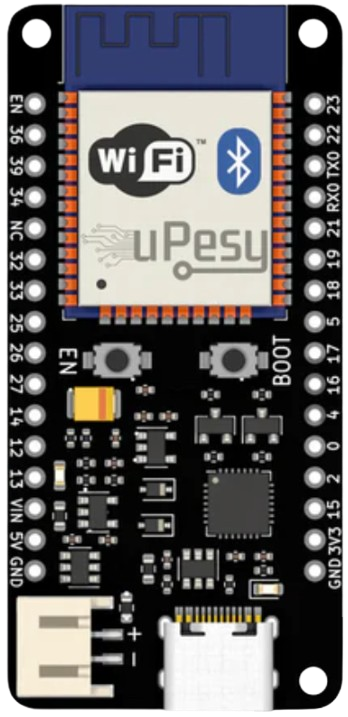
Pin Configuration and Descriptions

The uPesy ESP32 Wroom Low Power DevKit features a 30-pin layout. Below is a summary of the pin configuration:

Pin Name Description
1 3V3 3.3V power output
2 GND Ground
3 EN Enable pin (active high)
4 IO0 GPIO0, used for boot mode selection
5 IO2 GPIO2, general-purpose I/O
6 IO4 GPIO4, general-purpose I/O
7 IO5 GPIO5, general-purpose I/O
8 IO12 GPIO12, general-purpose I/O
9 IO13 GPIO13, general-purpose I/O
10 IO14 GPIO14, general-purpose I/O
11 IO15 GPIO15, general-purpose I/O
12 IO16 GPIO16, general-purpose I/O
13 IO17 GPIO17, general-purpose I/O
14 IO18 GPIO18, general-purpose I/O
15 IO19 GPIO19, general-purpose I/O
16 IO21 GPIO21, general-purpose I/O
17 IO22 GPIO22, general-purpose I/O
18 IO23 GPIO23, general-purpose I/O
19 IO25 GPIO25, general-purpose I/O
20 IO26 GPIO26, general-purpose I/O
21 IO27 GPIO27, general-purpose I/O
22 IO32 GPIO32, ADC input
23 IO33 GPIO33, ADC input
24 IO34 GPIO34, ADC input (input-only)
25 IO35 GPIO35, ADC input (input-only)
26 VIN Input voltage (5V via USB or external power)
27 TXD0 UART0 TX
28 RXD0 UART0 RX
29 DAC1 Digital-to-Analog Converter 1
30 DAC2 Digital-to-Analog Converter 2

Usage Instructions

How to Use the Component in a Circuit

  1. Powering the Board:

    • Connect the board to a computer or USB power source using a Micro-USB cable.
    • Alternatively, supply 5V to the VIN pin for external power.
  2. Programming the Board:

    • Install the Arduino IDE or PlatformIO for development.
    • Add the ESP32 board support package to your IDE.
    • Select the correct board (ESP32 Dev Module) and port in the IDE settings.
  3. Connecting Peripherals:

    • Use the GPIO pins to connect sensors, actuators, or other peripherals.
    • Ensure that the voltage levels of connected devices are compatible with the 3.3V logic of the ESP32.
  4. Uploading Code:

    • Write your code in the IDE and upload it to the board via the USB connection.
    • Press the "EN" button to reset the board if needed.

Important Considerations and Best Practices

  • Voltage Levels: Avoid applying voltages higher than 3.3V to the GPIO pins to prevent damage.
  • Deep Sleep Mode: Use the deep sleep mode to minimize power consumption in battery-powered applications.
  • Boot Mode: To enter bootloader mode, hold the IO0 pin low while resetting the board.
  • External Antenna: For better Wi-Fi performance, consider using an external antenna if supported.

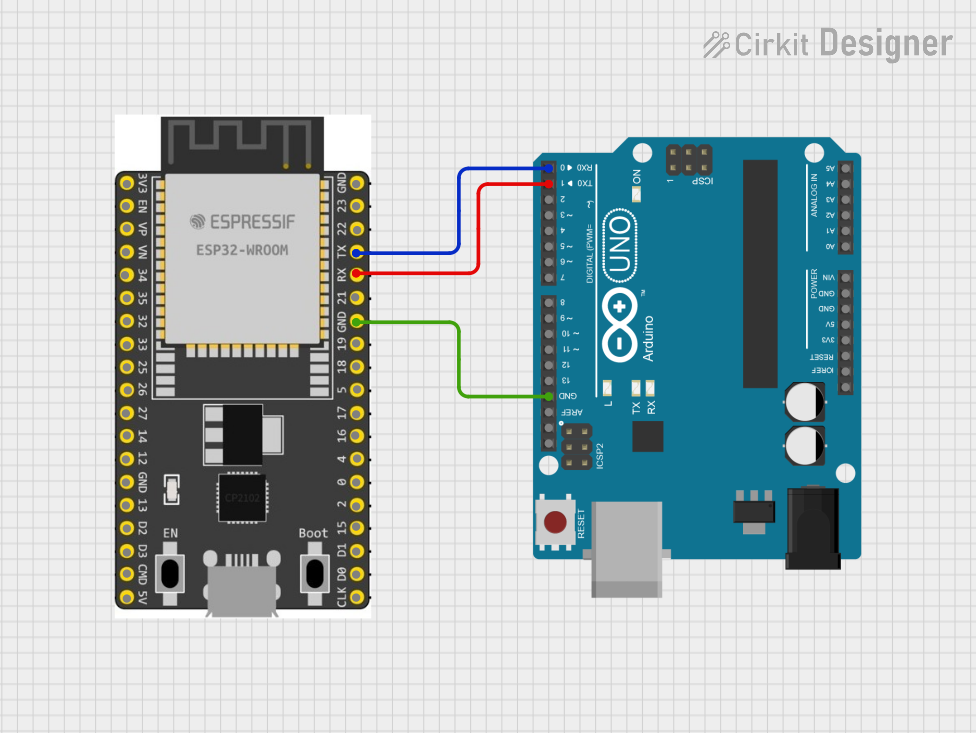
Example Code for Arduino UNO Integration

Below is an example of how to blink an LED connected to GPIO2 of the uPesy ESP32 Wroom Low Power DevKit:

// Example: Blink an LED connected to GPIO2 of the uPesy ESP32 Wroom Low Power DevKit

// Define the GPIO pin for the LED
const int ledPin = 2;

void setup() {
  // Initialize the LED pin as an output
  pinMode(ledPin, OUTPUT);
}

void loop() {
  // Turn the LED on
  digitalWrite(ledPin, HIGH);
  delay(1000); // Wait for 1 second

  // Turn the LED off
  digitalWrite(ledPin, LOW);
  delay(1000); // Wait for 1 second
}

Troubleshooting and FAQs

Common Issues and Solutions

  1. The board is not detected by the computer:

    • Ensure the USB cable is functional and supports data transfer.
    • Install the correct USB-to-serial driver for the ESP32.
  2. Code upload fails:

    • Check that the correct board and port are selected in the IDE.
    • Hold the IO0 pin low while pressing the "EN" button to enter bootloader mode.
  3. Wi-Fi connection issues:

    • Verify the SSID and password in your code.
    • Ensure the board is within range of the Wi-Fi router.
  4. High power consumption:

    • Use deep sleep mode to reduce power usage.
    • Disconnect unused peripherals to minimize current draw.

FAQs

  • Q: Can I power the board with a battery?
    A: Yes, you can use a 3.7V LiPo battery connected to the VIN pin or a 5V power source.

  • Q: Does the board support OTA updates?
    A: Yes, the ESP32 supports Over-The-Air (OTA) updates for wireless code uploads.

  • Q: Can I use the board with MicroPython?
    A: Yes, the ESP32 is compatible with MicroPython. Flash the MicroPython firmware to get started.

  • Q: What is the maximum Wi-Fi range?
    A: The range depends on environmental factors but typically extends up to 100 meters in open space.