How to Use DC 9-60V Motor controller: Examples, Pinouts, and Specs
Introduction
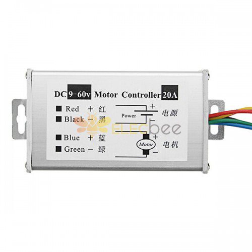
The DC 9-60V Motor Controller is a versatile device designed to regulate the speed and direction of DC motors operating within a voltage range of 9 to 60 volts. It provides precise control over motor performance, making it ideal for applications requiring variable speed, smooth acceleration, and bidirectional operation. This component is widely used in robotics, electric vehicles, conveyor systems, and other motor-driven systems.
Explore Projects Built with DC 9-60V Motor controller

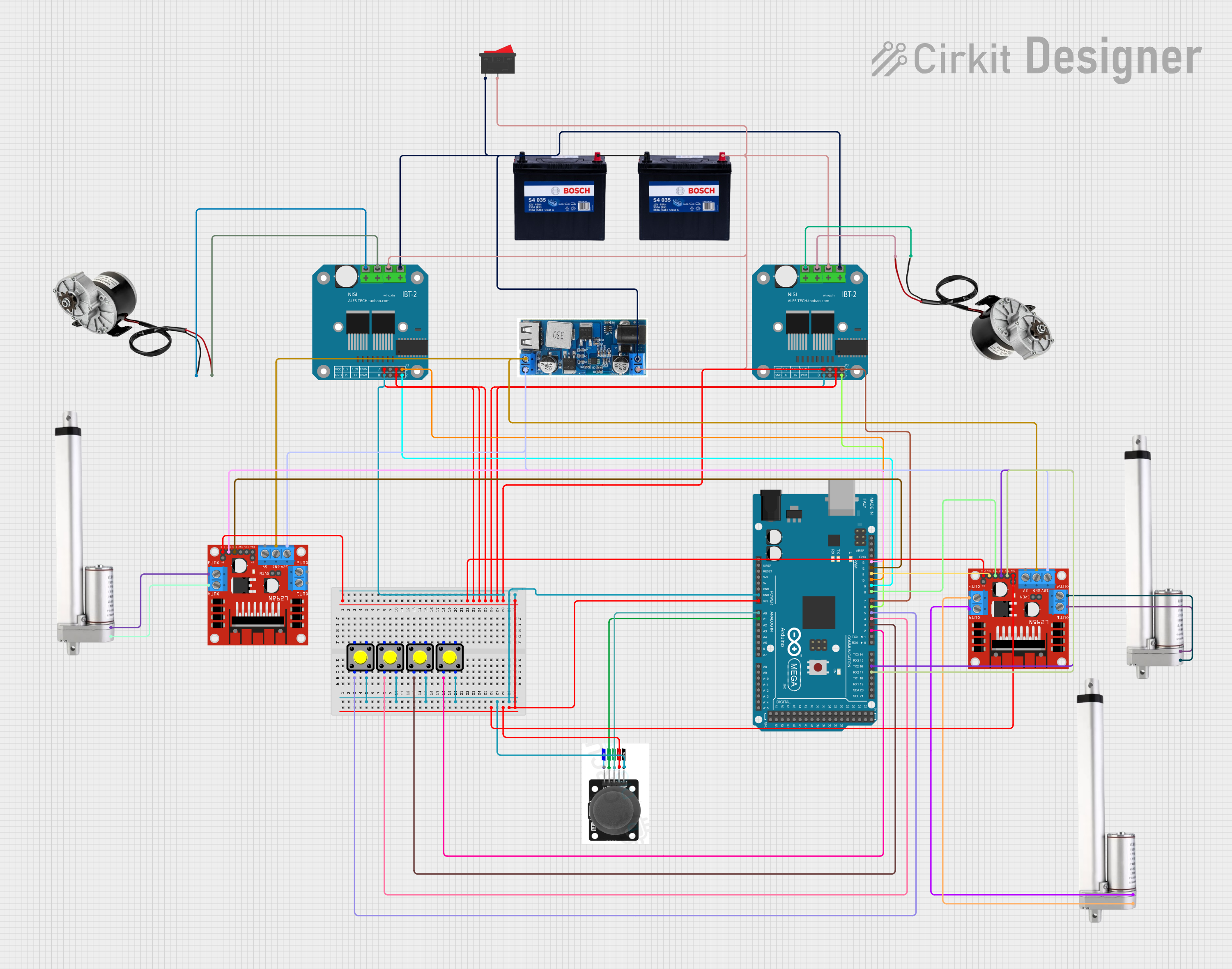
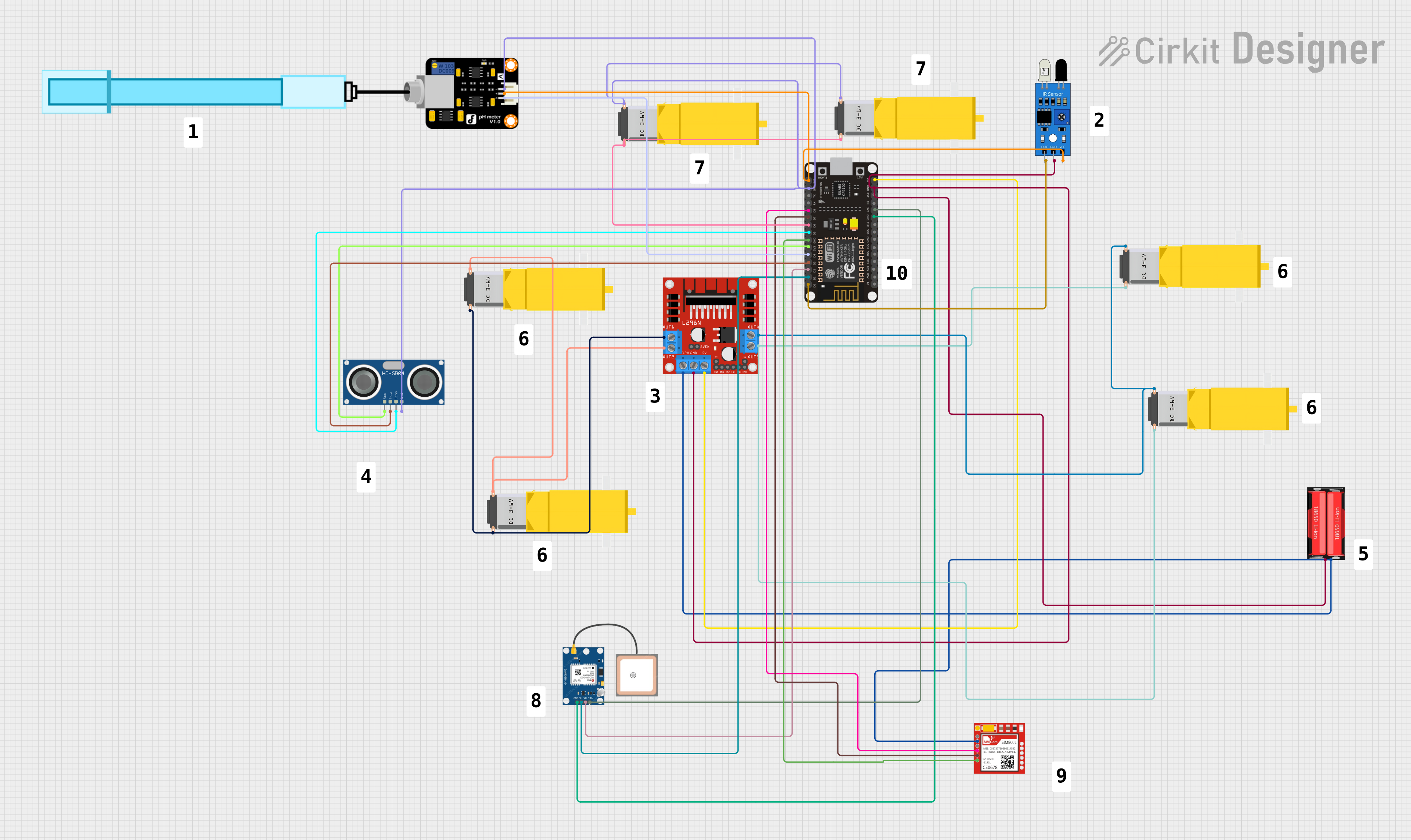
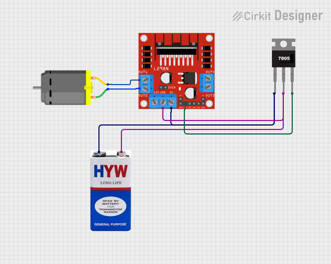
Explore Projects Built with DC 9-60V Motor controller
Common Applications and Use Cases
- Robotics: Controlling motor speed and direction for robotic arms and wheels.
- Electric vehicles: Managing motor performance in e-bikes, scooters, and carts.
- Conveyor systems: Adjusting speed for material handling and automation.
- DIY projects: Building custom motorized devices and tools.
- Industrial automation: Precise motor control in manufacturing equipment.
Technical Specifications
The DC 9-60V Motor Controller is designed to handle a wide range of motor control requirements. Below are its key technical details:
Key Technical Details
| Parameter | Specification |
|---|---|
| Input Voltage Range | 9V to 60V DC |
| Output Current | Up to 30A (varies by model) |
| Control Mode | Pulse Width Modulation (PWM) |
| PWM Frequency | 15 kHz to 25 kHz |
| Speed Adjustment Range | 0% to 100% |
| Direction Control | Forward and Reverse |
| Efficiency | ≥ 90% |
| Operating Temperature | -20°C to 50°C |
| Dimensions | Varies by model (e.g., 100x60x30 mm) |
Pin Configuration and Descriptions
The motor controller typically includes the following terminals for connections:
| Pin/Terminal Name | Description |
|---|---|
| VIN+ | Positive input voltage terminal (connect to power supply +) |
| VIN- | Negative input voltage terminal (connect to power supply -) |
| M+ | Positive motor terminal (connect to motor +) |
| M- | Negative motor terminal (connect to motor -) |
| PWM Input | Optional input for external PWM signal (for speed control) |
| Direction Control | Optional input for controlling motor direction (e.g., forward/reverse) |
| Potentiometer | Built-in or external potentiometer for manual speed adjustment |
Usage Instructions
How to Use the Component in a Circuit
- Power Supply Connection: Connect the VIN+ and VIN- terminals to a DC power supply within the specified voltage range (9-60V). Ensure the power supply can provide sufficient current for the motor.
- Motor Connection: Connect the motor terminals (M+ and M-) to the DC motor. Ensure proper polarity for the desired initial direction.
- Speed Control:
- Use the built-in potentiometer (if available) to adjust the motor speed.
- Alternatively, connect an external PWM signal to the PWM input terminal for precise speed control.
- Direction Control:
- If the controller supports direction control, use the direction control input to toggle between forward and reverse operation.
- Some controllers may require a switch or logic signal for this purpose.
- Testing: Power on the circuit and gradually adjust the speed or direction to verify proper operation.
Important Considerations and Best Practices
- Voltage Compatibility: Ensure the input voltage matches the motor controller's specifications to avoid damage.
- Current Rating: Verify that the motor's current draw does not exceed the controller's maximum current rating.
- Heat Dissipation: Use proper heat sinks or cooling mechanisms if the controller operates at high currents for extended periods.
- Wiring: Use appropriately rated wires for power and motor connections to prevent overheating or voltage drops.
- Polarity: Double-check all connections to avoid reverse polarity, which can damage the controller or motor.
Example: Using with Arduino UNO
The DC 9-60V Motor Controller can be controlled using an Arduino UNO to provide a PWM signal for speed control and a digital signal for direction control. Below is an example code snippet:
// Define pins for PWM and direction control
const int pwmPin = 9;       // PWM output pin for speed control
const int dirPin = 8;       // Digital output pin for direction control

void setup() {
  pinMode(pwmPin, OUTPUT);  // Set PWM pin as output
  pinMode(dirPin, OUTPUT);  // Set direction pin as output
}

void loop() {
  // Set motor direction to forward
  digitalWrite(dirPin, HIGH);  // HIGH for forward, LOW for reverse

  // Gradually increase motor speed
  for (int speed = 0; speed <= 255; speed += 5) {
    analogWrite(pwmPin, speed);  // Write PWM value (0-255)
    delay(100);                  // Wait 100ms
  }

  // Gradually decrease motor speed
  for (int speed = 255; speed >= 0; speed -= 5) {
    analogWrite(pwmPin, speed);  // Write PWM value (0-255)
    delay(100);                  // Wait 100ms
  }

  // Reverse motor direction
  digitalWrite(dirPin, LOW);    // Set direction to reverse
  delay(2000);                  // Run in reverse for 2 seconds
}
Troubleshooting and FAQs
Common Issues and Solutions
Motor Does Not Run:
- Cause: Incorrect wiring or insufficient power supply.
- Solution: Double-check all connections and ensure the power supply meets the voltage and current requirements.
Motor Runs in the Wrong Direction:
- Cause: Motor terminals are reversed or incorrect direction control signal.
- Solution: Swap the motor connections (M+ and M-) or adjust the direction control input.
Overheating:
- Cause: Excessive current draw or poor ventilation.
- Solution: Use a heat sink or fan for cooling and ensure the motor's current is within the controller's rating.
PWM Signal Not Working:
- Cause: Incorrect PWM frequency or signal level.
- Solution: Verify the PWM signal matches the controller's specifications (e.g., 15-25 kHz).
Controller Not Responding:
- Cause: Faulty component or incorrect setup.
- Solution: Inspect the controller for damage and ensure all connections are secure.
FAQs
Q1: Can I use this controller with a 12V motor?
A1: Yes, the controller supports a wide voltage range (9-60V), so it is compatible with 12V motors.
Q2: What happens if I exceed the current rating?
A2: Exceeding the current rating may damage the controller. Use a motor with a current draw within the specified limit.
Q3: Can I control multiple motors with one controller?
A3: No, this controller is designed for a single motor. Use separate controllers for multiple motors.
Q4: Is it safe to use this controller outdoors?
A4: Unless specified as weatherproof, the controller should be used in a dry, protected environment.
Q5: Can I use a battery as the power source?
A5: Yes, as long as the battery voltage is within the 9-60V range and can supply sufficient current.