How to Use REED SWITCH MODULE: Examples, Pinouts, and Specs
Introduction
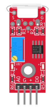
- A reed switch module consists of a reed switch encapsulated in a protective housing, often with additional circuitry. It operates by closing or opening an electrical circuit in response to a magnetic field.
- This module is widely used in sensing applications, such as security systems (e.g., door/window sensors), position detection, proximity sensing, and robotics. Its ability to detect magnetic fields makes it a reliable and cost-effective solution for various automation and monitoring tasks.
Explore Projects Built with REED SWITCH MODULE
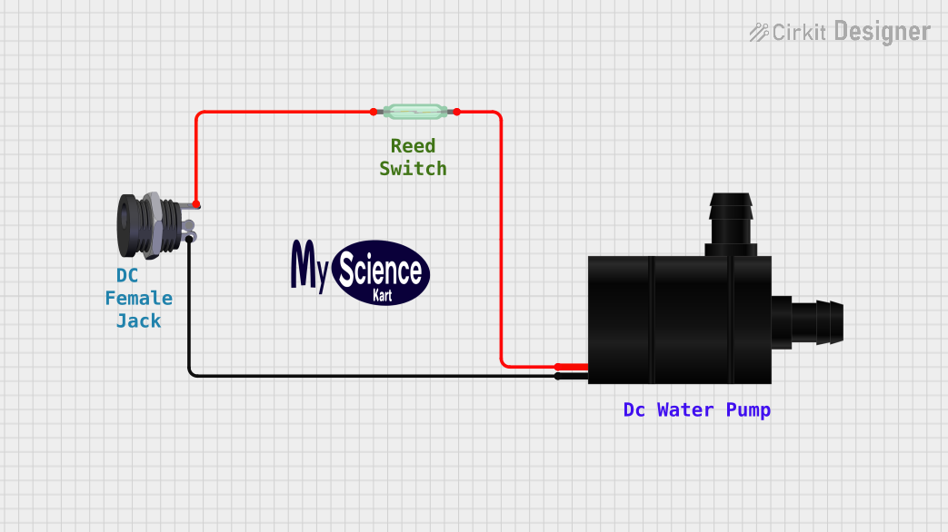
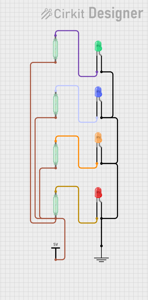
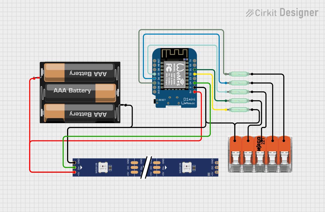
Explore Projects Built with REED SWITCH MODULE
Technical Specifications
- Operating Voltage: 3.3V to 5V DC
- Switch Type: Normally Open (NO) or Normally Closed (NC), depending on the module design
- Maximum Switching Voltage: Typically 100V DC (reed switch only)
- Maximum Switching Current: Typically 0.5A (reed switch only)
- Response Time: ~0.5ms (varies by module)
- Module Dimensions: Varies, typically ~30mm x 15mm x 10mm
- Output Type: Digital (HIGH or LOW signal)
Pin Configuration and Descriptions
| Pin Name | Description |
|---|---|
| VCC | Power supply pin. Connect to 3.3V or 5V DC. |
| GND | Ground pin. Connect to the ground of the power supply. |
| OUT | Digital output pin. Outputs HIGH (1) when the reed switch is open, and LOW (0) when closed. |
Usage Instructions
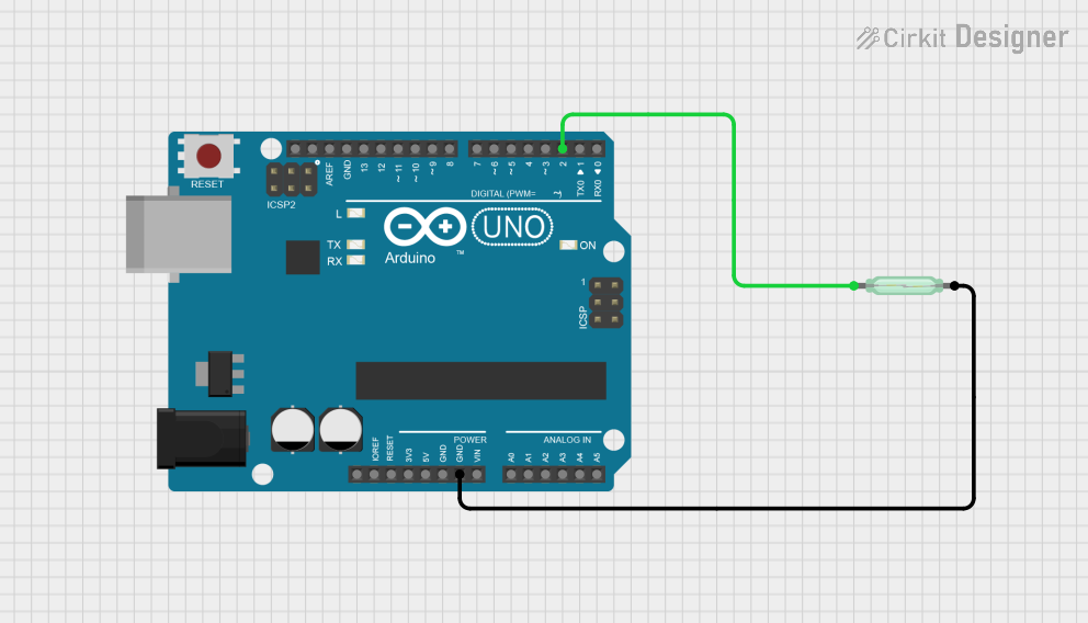
How to Use the Reed Switch Module in a Circuit
Power the Module:
- Connect the
VCCpin to a 3.3V or 5V DC power source. - Connect the
GNDpin to the ground of the power source.
- Connect the
Connect the Output:
- Connect the
OUTpin to a digital input pin of a microcontroller (e.g., Arduino UNO). - Use a pull-up resistor if the module does not have one built-in.
- Connect the
Place a Magnet:
- Position a magnet near the reed switch to trigger it. The module will output a LOW signal when the reed switch closes (magnet nearby) and a HIGH signal when the reed switch is open (magnet far away).
Important Considerations and Best Practices
- Magnet Placement: Ensure the magnet is aligned properly with the reed switch for reliable operation.
- Debouncing: Reed switches may produce noise or "bouncing" when switching states. Use software debouncing in your code to filter out false triggers.
- Current Limitation: Avoid exceeding the maximum current and voltage ratings of the reed switch to prevent damage.
- Environmental Factors: Keep the module away from strong electromagnetic interference (EMI) sources, as they may affect its performance.
Example Code for Arduino UNO
// Reed Switch Module Example Code for Arduino UNO
// This code reads the state of the reed switch and prints it to the Serial Monitor.

const int reedSwitchPin = 2; // Connect the OUT pin of the module to digital pin 2
int reedState = 0;           // Variable to store the state of the reed switch

void setup() {
  pinMode(reedSwitchPin, INPUT); // Set the reed switch pin as input
  Serial.begin(9600);           // Initialize serial communication at 9600 baud
}

void loop() {
  reedState = digitalRead(reedSwitchPin); // Read the state of the reed switch

  if (reedState == LOW) {
    // Reed switch is closed (magnet nearby)
    Serial.println("Magnet Detected!");
  } else {
    // Reed switch is open (magnet far away)
    Serial.println("No Magnet Detected.");
  }

  delay(500); // Wait for 500ms before reading again
}
Troubleshooting and FAQs
Common Issues and Solutions
The module does not detect the magnet:
- Ensure the magnet is strong enough and properly aligned with the reed switch.
- Check the power connections to the module (VCC and GND).
False triggers or unstable output:
- Add software debouncing in your code to filter out noise.
- Verify that the module is not exposed to strong EMI sources.
Output signal is always HIGH or LOW:
- Inspect the reed switch for physical damage.
- Confirm that the
OUTpin is properly connected to the microcontroller.
FAQs
Q: Can I use the reed switch module with a 12V power supply?
A: No, the module is designed to operate at 3.3V to 5V DC. Using a higher voltage may damage the module.
Q: How far can the magnet be placed from the reed switch?
A: The distance depends on the strength of the magnet and the sensitivity of the reed switch. Typically, it ranges from a few millimeters to a few centimeters.
Q: Can the reed switch module detect non-magnetic objects?
A: No, the reed switch operates based on magnetic fields and cannot detect non-magnetic objects.
Q: Is the reed switch module polarity-sensitive?
A: No, the reed switch itself is not polarity-sensitive, but ensure proper connections for the module's circuitry.