
How to Use ESP32 TFT 3.5 CYD: Examples, Pinouts, and Specs
 Design with ESP32 TFT 3.5 CYD in Cirkit Designer
Introduction
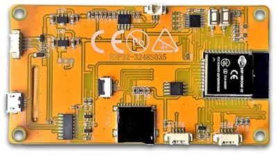
The ESP32 TFT 3.5 CYD is a 3.5-inch TFT display module integrated with an ESP32 microcontroller. This versatile component combines wireless communication capabilities (Wi-Fi and Bluetooth) with a high-resolution graphical display, making it ideal for a wide range of embedded applications. It is particularly suited for IoT projects, smart home devices, portable displays, and interactive user interfaces.
Explore Projects Built with ESP32 TFT 3.5 CYD
 Open Project in Cirkit Designer
 Open Project in Cirkit Designer
 Open Project in Cirkit Designer
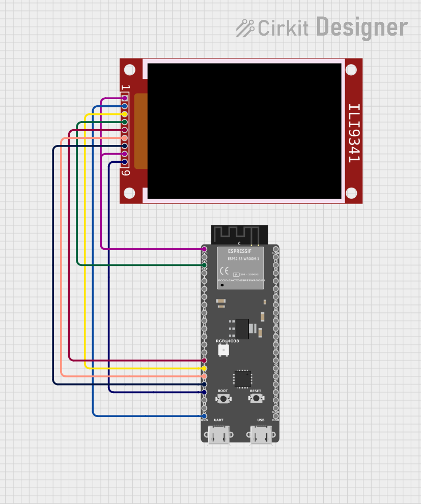 Open Project in Cirkit Designer
Explore Projects Built with ESP32 TFT 3.5 CYD
Open Project in Cirkit DesignerOpen Project in Cirkit DesignerOpen Project in Cirkit DesignerOpen Project in Cirkit DesignerCommon Applications
- IoT dashboards and control panels
- Smart home automation systems
- Portable gaming devices
- Industrial monitoring displays
- Educational and prototyping projects
Technical Specifications
Key Technical Details
| Parameter | Specification |
|---|---|
| Display Size | 3.5 inches |
| Resolution | 480 x 320 pixels |
| Display Type | TFT LCD with capacitive touch support |
| Microcontroller | ESP32 (dual-core, 240 MHz) |
| Communication Protocols | Wi-Fi 802.11 b/g/n, Bluetooth v4.2 |
| Operating Voltage | 3.3V |
| Input Voltage Range | 5V (via USB or external power supply) |
| Touch Interface | SPI |
| Display Interface | SPI |
| Flash Memory | 4MB |
| SRAM | 520KB |
| Operating Temperature | -20°C to 70°C |
Pin Configuration and Descriptions
The ESP32 TFT 3.5 CYD module has a set of pins for power, communication, and control. Below is the pinout description:
| Pin Name | Function | Description |
|---|---|---|
| VIN | Power Input | Accepts 5V input from USB or external power supply. |
| GND | Ground | Common ground for the module. |
| 3V3 | 3.3V Output | Provides 3.3V output for external components. |
| MOSI | SPI Master Out Slave In | SPI data line for communication with the display. |
| MISO | SPI Master In Slave Out | SPI data line for receiving data from the display (if applicable). |
| SCK | SPI Clock | SPI clock signal for synchronization. |
| CS | Chip Select | Selects the TFT display for SPI communication. |
| DC | Data/Command Control | Determines whether data or commands are sent to the display. |
| RST | Reset | Resets the display module. |
| T_IRQ | Touch Interrupt | Interrupt pin for touch functionality. |
| T_CS | Touch Chip Select | Selects the touch controller for SPI communication. |
| EN | Enable | Enables the ESP32 module. |
| IO Pins | General Purpose I/O | Configurable pins for additional peripherals or sensors. |
Usage Instructions
How to Use the Component in a Circuit
- Powering the Module: Connect the
VINpin to a 5V power source and theGNDpin to ground. The module will regulate the voltage internally to 3.3V. - Connecting to an MCU: Use the SPI pins (
MOSI,MISO,SCK,CS,DC,RST) to interface the display with a microcontroller or development board. - Touch Functionality: Connect the
T_CSandT_IRQpins to the microcontroller for touch input functionality. - Programming the ESP32: Use the USB interface to upload code to the ESP32 microcontroller. Ensure the correct drivers are installed on your computer.
Important Considerations and Best Practices
- Power Supply: Ensure a stable 5V power supply to avoid voltage fluctuations that may cause the display to malfunction.
- SPI Speed: Configure the SPI clock speed appropriately to balance performance and stability. A typical value is 40 MHz.
- Library Support: Use libraries such as
TFT_eSPIfor Arduino IDE orlvglfor advanced graphical interfaces. - Heat Management: If the module operates in high-temperature environments, consider adding a heatsink to the ESP32.
Example Code for Arduino UNO
Below is an example of how to initialize and display text on the ESP32 TFT 3.5 CYD using the TFT_eSPI library:
#include <TFT_eSPI.h> // Include the TFT library

TFT_eSPI tft = TFT_eSPI(); // Create an instance of the TFT object

void setup() {
  tft.init(); // Initialize the display
  tft.setRotation(1); // Set display orientation (1 = landscape)
  tft.fillScreen(TFT_BLACK); // Clear the screen with black color

  tft.setTextColor(TFT_WHITE, TFT_BLACK); // Set text color (white on black)
  tft.setTextSize(2); // Set text size
  tft.setCursor(10, 10); // Set cursor position
  tft.println("Hello, ESP32 TFT!"); // Print text to the display
}

void loop() {
  // Add your code here for dynamic updates
}
Notes:
- Install the
TFT_eSPIlibrary from the Arduino Library Manager before running the code. - Configure the
User_Setup.hfile in theTFT_eSPIlibrary to match the pin connections of your module.
Troubleshooting and FAQs
Common Issues and Solutions
Display Not Turning On:
- Ensure the
VINpin is connected to a stable 5V power source. - Verify all ground connections are secure.
- Ensure the
No Output on the Display:
- Check the SPI connections (
MOSI,MISO,SCK,CS,DC,RST) for loose or incorrect wiring. - Confirm that the correct SPI pins are defined in the code.
- Check the SPI connections (
Touch Functionality Not Working:
- Verify the
T_CSandT_IRQpins are connected properly. - Ensure the touch controller is enabled in the library configuration.
- Verify the
Flickering or Artifacts on the Screen:
- Reduce the SPI clock speed in the code.
- Check for electromagnetic interference from nearby components.
FAQs
Q: Can I use this module with a 5V microcontroller like Arduino UNO?
A: Yes, but you will need a logic level shifter to convert the 5V signals to 3.3V for the ESP32 and TFT display.
Q: Does the module support capacitive touch?
A: Yes, the ESP32 TFT 3.5 CYD includes capacitive touch functionality via the SPI interface.
Q: Can I use this module without Wi-Fi or Bluetooth?
A: Yes, the ESP32 can operate in standalone mode without using its wireless features.
Q: What is the maximum SPI clock speed supported?
A: The module typically supports SPI clock speeds up to 40 MHz, but this may vary depending on the specific use case and wiring quality.