How to Use MP6550 Single Brushed DC Motor Driver Carrier: Examples, Pinouts, and Specs
Introduction
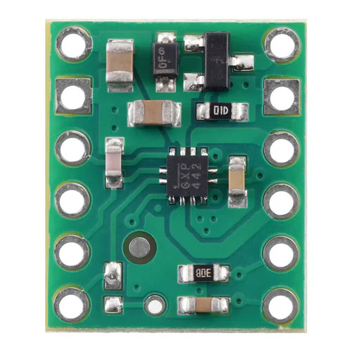
The MP6550 Single Brushed DC Motor Driver Carrier, manufactured by Pololu, is a compact and efficient motor driver designed to control the speed and direction of a single brushed DC motor. It features a wide operating voltage range, built-in protection against overcurrent and thermal overload, and a simple interface for easy integration into various projects. This carrier board is ideal for applications requiring precise motor control, such as robotics, automation systems, and hobbyist projects.
Explore Projects Built with MP6550 Single Brushed DC Motor Driver Carrier
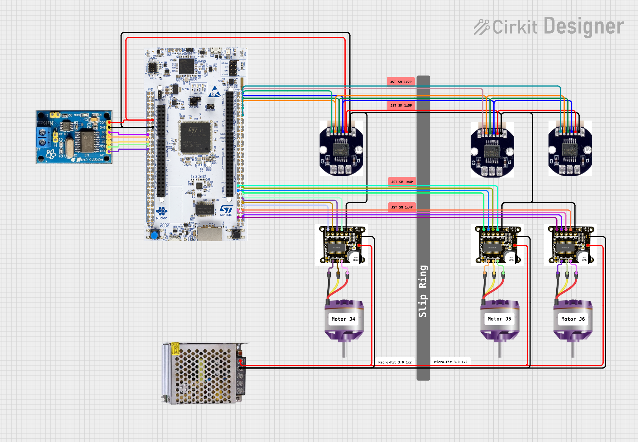

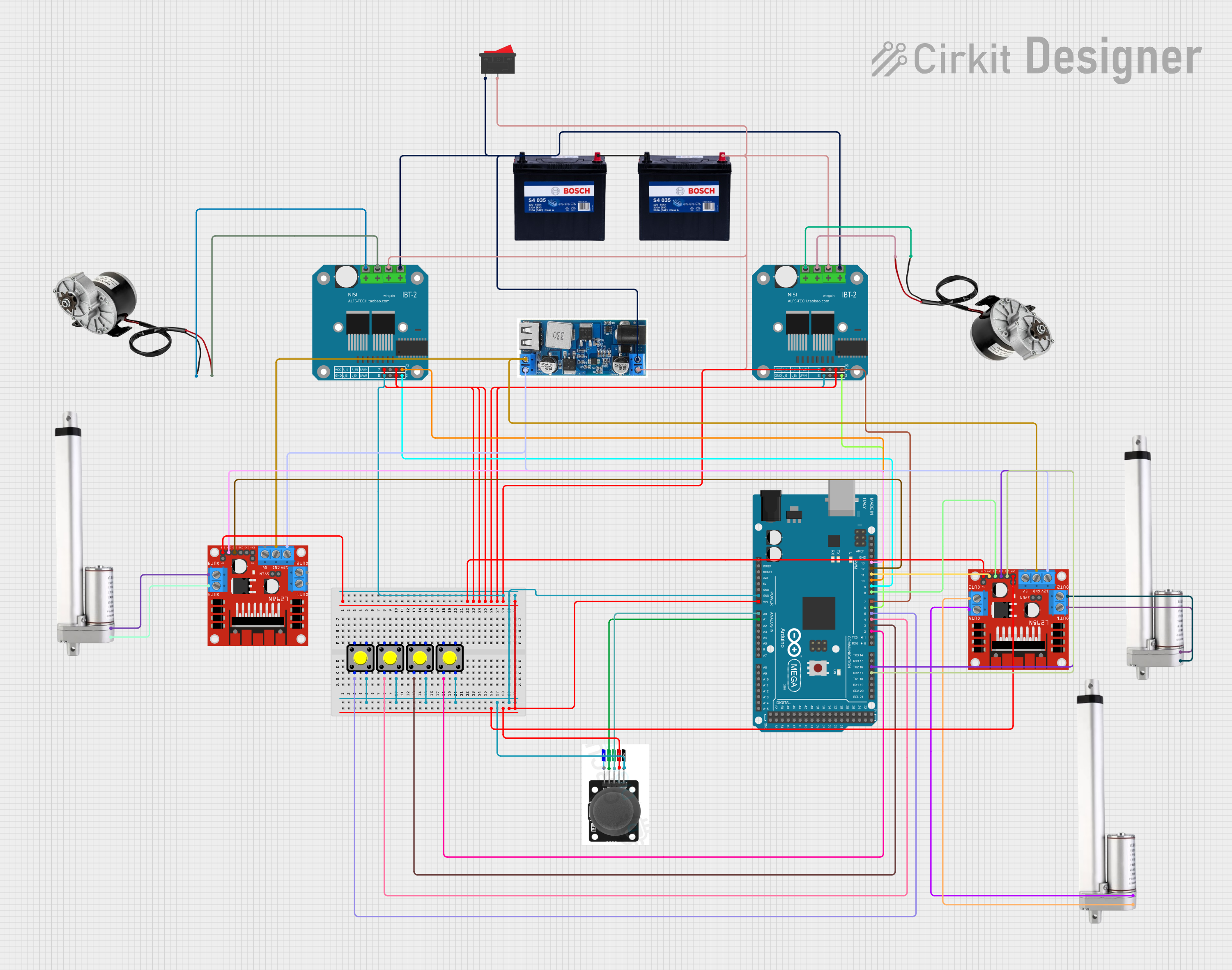
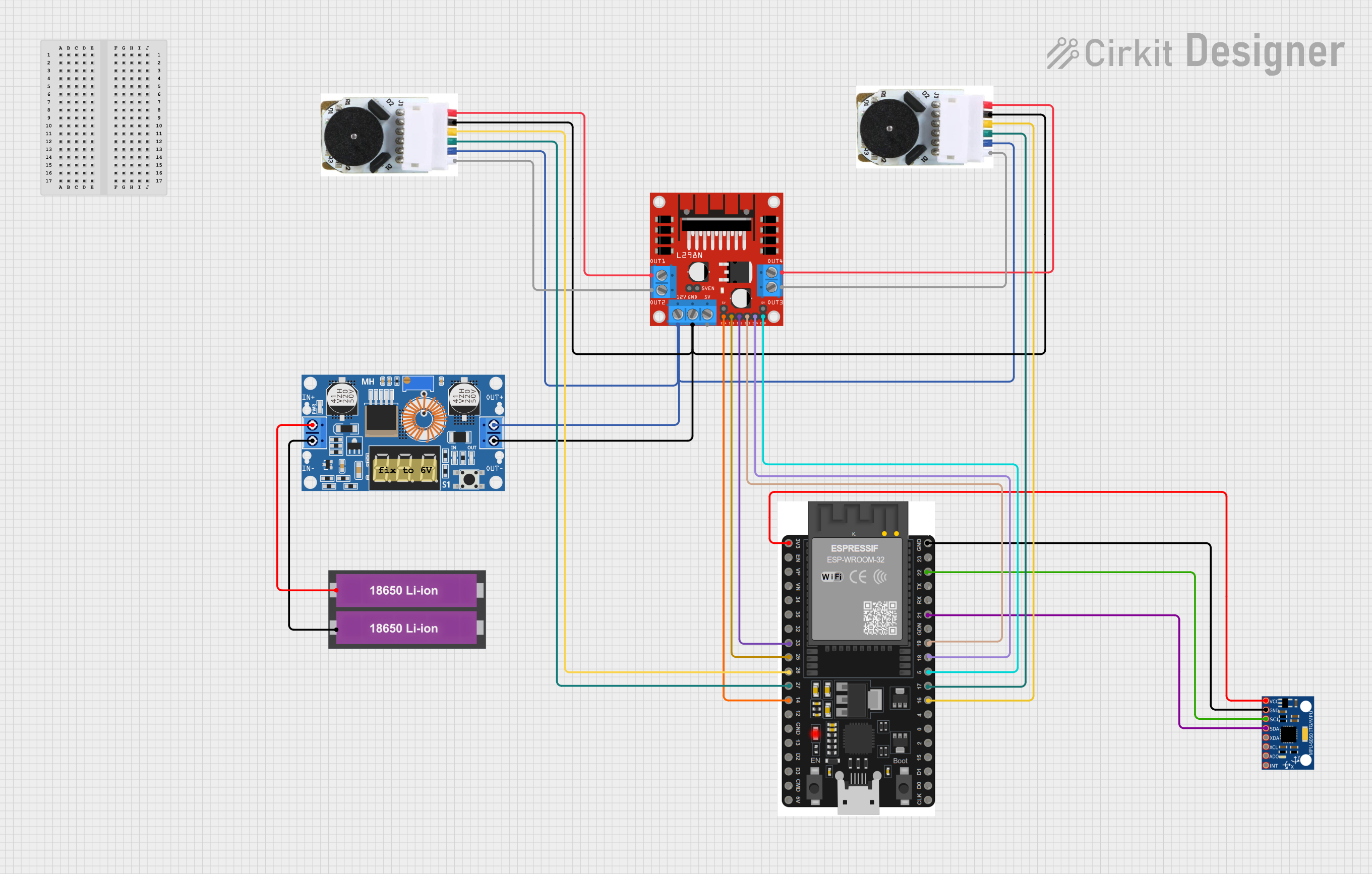
Explore Projects Built with MP6550 Single Brushed DC Motor Driver Carrier
Common Applications
- Robotics and mechatronics
- Automated conveyor systems
- Remote-controlled vehicles
- DIY electronics and hobbyist projects
- Educational kits for motor control
Technical Specifications
The MP6550 motor driver offers robust performance in a small form factor. Below are its key technical details:
Key Specifications
| Parameter | Value |
|---|---|
| Operating Voltage Range | 2.7 V to 16 V |
| Continuous Output Current | Up to 1.8 A (with sufficient cooling) |
| Peak Output Current | 2.5 A (for short durations) |
| Control Interface | PWM and direction control |
| Logic Voltage Range | 1.8 V to 5 V |
| Built-in Protections | Overcurrent, thermal shutdown, undervoltage lockout |
| Dimensions | 0.6" × 0.8" × 0.1" (15 mm × 20 mm × 3 mm) |
| Weight | 0.5 g |
Pin Configuration and Descriptions
The MP6550 carrier board has six pins for interfacing with your circuit. The table below describes each pin:
| Pin Name | Description |
|---|---|
| VIN | Motor power supply input (2.7 V to 16 V). Connect to the positive terminal of your motor power source. |
| GND | Ground connection. Connect to the ground of your power supply and control circuit. |
| OUTA | Motor output A. Connect to one terminal of the brushed DC motor. |
| OUTB | Motor output B. Connect to the other terminal of the brushed DC motor. |
| PWM | PWM input for speed control. Accepts a PWM signal (1.8 V to 5 V logic). |
| DIR | Direction control input. High or low logic determines motor rotation direction. |
Usage Instructions
Connecting the MP6550 to a Circuit
- Power Supply: Connect the VIN pin to a power source (2.7 V to 16 V) capable of supplying sufficient current for your motor. Connect the GND pin to the ground of the power source.
- Motor Connections: Attach the two terminals of your brushed DC motor to the OUTA and OUTB pins.
- Control Signals:
- Connect the PWM pin to a PWM-capable output pin of your microcontroller (e.g., Arduino).
- Connect the DIR pin to a digital output pin of your microcontroller to control the motor's direction.
- Logic Ground: Ensure the ground of your microcontroller is connected to the GND pin of the MP6550.
Important Considerations
- Cooling: For continuous operation at higher currents, ensure adequate cooling (e.g., heat sinks or airflow) to prevent thermal shutdown.
- PWM Frequency: The MP6550 supports PWM frequencies up to 100 kHz. For most applications, a frequency between 10 kHz and 20 kHz is recommended to minimize audible noise.
- Protection Features: The driver includes overcurrent and thermal protection. If the driver shuts down unexpectedly, check for excessive current draw or overheating.
Example Code for Arduino UNO
Below is an example of how to control the MP6550 with an Arduino UNO:
// Define pin connections
const int pwmPin = 9;  // PWM pin connected to MP6550 PWM input
const int dirPin = 8;  // Direction pin connected to MP6550 DIR input

void setup() {
  // Set pin modes
  pinMode(pwmPin, OUTPUT);
  pinMode(dirPin, OUTPUT);
}

void loop() {
  // Rotate motor in one direction at 50% speed
  digitalWrite(dirPin, HIGH);  // Set direction
  analogWrite(pwmPin, 128);    // Set speed (128/255 = 50%)
  delay(2000);                 // Run for 2 seconds

  // Rotate motor in the opposite direction at 75% speed
  digitalWrite(dirPin, LOW);   // Change direction
  analogWrite(pwmPin, 192);    // Set speed (192/255 = 75%)
  delay(2000);                 // Run for 2 seconds

  // Stop the motor
  analogWrite(pwmPin, 0);      // Set speed to 0
  delay(1000);                 // Wait for 1 second
}
Best Practices
- Use decoupling capacitors near the VIN pin to reduce noise and improve stability.
- Avoid exceeding the voltage and current ratings to prevent damage to the driver.
- Test your circuit with a lower current motor before connecting high-power motors.
Troubleshooting and FAQs
Common Issues and Solutions
Motor Not Spinning
- Cause: Incorrect wiring or insufficient power supply.
- Solution: Double-check all connections and ensure the power supply meets the motor's requirements.
Driver Overheating
- Cause: Excessive current draw or inadequate cooling.
- Solution: Use a motor with lower current requirements or add a heat sink to the driver.
PWM Signal Not Working
- Cause: Incorrect PWM frequency or logic level mismatch.
- Solution: Verify that the PWM signal is within the supported frequency range (up to 100 kHz) and logic level (1.8 V to 5 V).
Motor Spins in the Wrong Direction
- Cause: DIR pin logic is reversed.
- Solution: Swap the logic level on the DIR pin or reverse the motor connections.
FAQs
Q: Can I use the MP6550 with a 3.3 V microcontroller?
A: Yes, the MP6550 supports logic levels as low as 1.8 V, making it compatible with 3.3 V microcontrollers.
Q: What happens if the motor draws more current than the driver can handle?
A: The MP6550 has built-in overcurrent protection. It will shut down temporarily to prevent damage.
Q: Can I control the motor speed without a PWM signal?
A: No, a PWM signal is required to control the motor speed. Without it, the motor will not operate.
Q: Is the MP6550 suitable for battery-powered applications?
A: Yes, its low operating voltage (2.7 V) and compact size make it ideal for battery-powered projects.
This concludes the documentation for the MP6550 Single Brushed DC Motor Driver Carrier. For further assistance, refer to the Pololu product page or contact their support team.