How to Use 7 segment: Examples, Pinouts, and Specs
Introduction
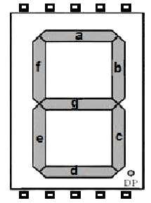
A 7-segment display is an electronic display device used to represent decimal numbers and some letters. Manufactured by IC, the IC 7 SEG is a versatile and widely used component in digital electronics. It consists of seven individual LED segments (labeled A through G) arranged in a rectangular pattern, with an optional decimal point. By illuminating specific segments, the display can represent digits from 0 to 9 and some alphabetic characters.
Explore Projects Built with 7 segment
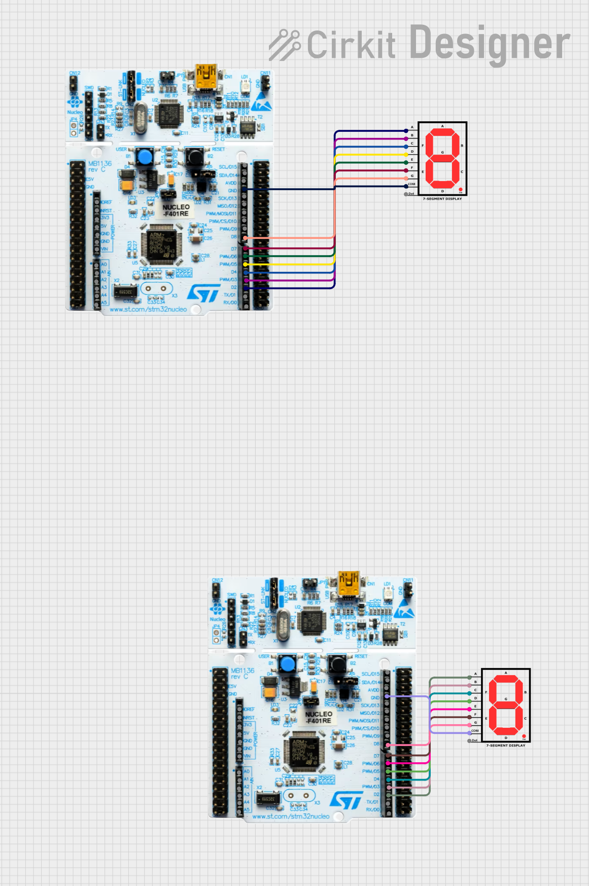
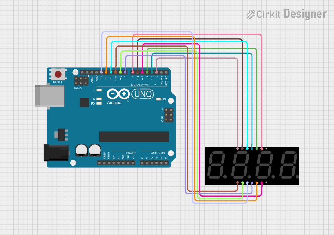
Explore Projects Built with 7 segment
Common Applications and Use Cases
- Digital clocks
- Electronic meters (e.g., voltmeters, ammeters)
- Calculators
- Scoreboards
- Embedded systems for numeric displays
Technical Specifications
Key Technical Details
- Manufacturer: IC
- Part ID: IC 7 SEG
- Operating Voltage: 2V to 3.3V (per segment, typical)
- Forward Current: 10mA to 20mA (per segment, typical)
- Power Dissipation: 70mW (maximum per segment)
- Display Type: Common Anode or Common Cathode (varies by model)
- Number of Segments: 7 (plus optional decimal point)
- Viewing Angle: 90° to 120°
- Operating Temperature: -40°C to +85°C
Pin Configuration and Descriptions
The IC 7 SEG display typically has 10 pins. The pin configuration depends on whether the display is a Common Anode or Common Cathode type. Below is a general pinout for a 7-segment display:
| Pin Number | Segment/Connection | Description |
|---|---|---|
| 1 | E | Controls segment E |
| 2 | D | Controls segment D |
| 3 | Common (Anode/Cathode) | Common connection for all segments |
| 4 | C | Controls segment C |
| 5 | Decimal Point (DP) | Controls the decimal point |
| 6 | B | Controls segment B |
| 7 | A | Controls segment A |
| 8 | Common (Anode/Cathode) | Common connection for all segments |
| 9 | F | Controls segment F |
| 10 | G | Controls segment G |
Note: Verify the datasheet for your specific IC 7 SEG model to confirm the pinout.
Usage Instructions
How to Use the Component in a Circuit
Determine the Type: Identify whether your 7-segment display is a Common Anode or Common Cathode type.
- In a Common Anode display, all anodes are connected together, and segments are activated by grounding their cathodes.
- In a Common Cathode display, all cathodes are connected together, and segments are activated by applying voltage to their anodes.
Connect the Pins:
- Connect the common pin (anode or cathode) to the appropriate power rail (VCC or GND).
- Use current-limiting resistors (typically 220Ω to 1kΩ) in series with each segment to prevent excessive current flow.
Control the Segments:
- Use a microcontroller (e.g., Arduino UNO) or a driver IC (e.g., 74HC595) to control the individual segments.
- Activate the segments by applying the appropriate voltage or ground signal.
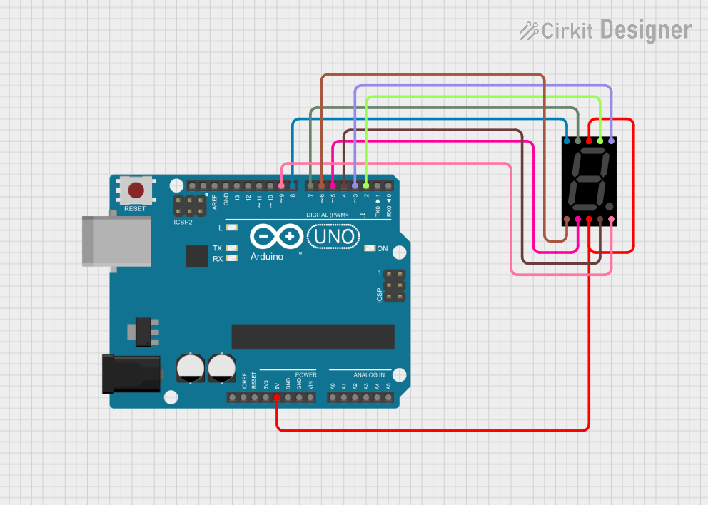
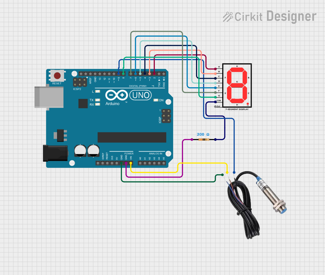
Example: Connecting to an Arduino UNO
Below is an example of how to connect and control a Common Cathode 7-segment display using an Arduino UNO:
Circuit Connections
- Connect the common cathode pin to GND.
- Connect each segment pin (A, B, C, D, E, F, G, DP) to Arduino digital pins through 220Ω resistors.
Arduino Code
// Define the Arduino pins connected to the 7-segment display segments
const int segmentPins[] = {2, 3, 4, 5, 6, 7, 8, 9}; // A, B, C, D, E, F, G, DP

// Define the segment patterns for digits 0-9
const byte digitPatterns[] = {
  0b00111111, // 0
  0b00000110, // 1
  0b01011011, // 2
  0b01001111, // 3
  0b01100110, // 4
  0b01101101, // 5
  0b01111101, // 6
  0b00000111, // 7
  0b01111111, // 8
  0b01101111  // 9
};

void setup() {
  // Set all segment pins as outputs
  for (int i = 0; i < 8; i++) {
    pinMode(segmentPins[i], OUTPUT);
  }
}

void loop() {
  // Display digits 0-9 in a loop
  for (int digit = 0; digit < 10; digit++) {
    displayDigit(digit);
    delay(1000); // Wait 1 second before displaying the next digit
  }
}

// Function to display a digit on the 7-segment display
void displayDigit(int digit) {
  byte pattern = digitPatterns[digit];
  for (int i = 0; i < 8; i++) {
    // Write HIGH or LOW to each segment pin based on the pattern
    digitalWrite(segmentPins[i], (pattern & (1 << i)) ? HIGH : LOW);
  }
}
Important Considerations and Best Practices
- Always use current-limiting resistors to protect the LEDs in the display.
- Verify the type (Common Anode or Common Cathode) before wiring the display.
- Avoid exceeding the maximum forward current and power dissipation ratings.
- For multiplexed displays, consider using a driver IC to simplify control and reduce the number of required microcontroller pins.
Troubleshooting and FAQs
Common Issues and Solutions
Some Segments Do Not Light Up
- Cause: Loose connections or damaged segments.
- Solution: Check the wiring and ensure all connections are secure. Test the display with a multimeter or a simple circuit to verify functionality.
All Segments Light Up Dimly
- Cause: Insufficient current or incorrect resistor values.
- Solution: Use appropriate current-limiting resistors (e.g., 220Ω). Ensure the power supply can provide sufficient current.
Display Does Not Work at All
- Cause: Incorrect wiring or wrong common type (anode/cathode).
- Solution: Double-check the wiring and verify the display type. Ensure the common pin is connected to the correct power rail.
Segments Flicker or Behave Erratically
- Cause: Poor connections or insufficient power supply.
- Solution: Check for loose wires and ensure the power supply is stable and adequate.
FAQs
Q: Can I control a 7-segment display without a microcontroller?
A: Yes, you can use switches, a BCD-to-7-segment decoder IC (e.g., 7447), or other logic circuits.Q: How do I display letters on a 7-segment display?
A: Letters like A, b, C, d, E, and F can be displayed by illuminating specific segments. Refer to segment patterns for each letter.Q: Can I use a 7-segment display with a 3.3V microcontroller?
A: Yes, as long as the forward voltage of the segments is compatible and current-limiting resistors are used.
This concludes the documentation for the IC 7 SEG 7-segment display.