Cirkit Designer
Your all-in-one circuit design IDE
Home /
Component Documentation
How to Use FTDI Programmer: Examples, Pinouts, and Specs
Introduction
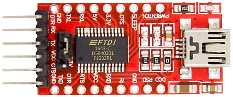
The FTDI Programmer is a crucial tool used for interfacing with devices that incorporate FTDI (Future Technology Devices International) chips. These chips are designed to facilitate USB communication with microcontrollers, serial communication devices, and other integrated circuits. The FTDI Programmer acts as a bridge between a USB port on a computer and the serial interface of a microcontroller or other circuits.
Explore Projects Built with FTDI Programmer
ATMEGA328 Microcontroller Circuit with Serial Programming Interface

This circuit features an ATMEGA328 microcontroller configured with a crystal oscillator for precise timing, and a pushbutton for reset functionality. An FTDI Programmer is connected for serial communication, allowing for programming and data exchange with the microcontroller.
ESP32 CAM Wi-Fi Controlled Camera with FTDI Programmer
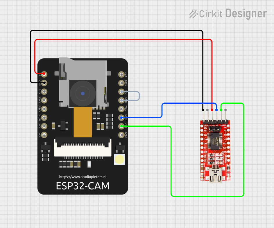
This circuit connects an ESP32 CAM module to an FTDI Programmer for programming and communication purposes. The FTDI Programmer provides power and ground to the ESP32 CAM, and the RX/TX lines are connected for serial communication. Additionally, GPIO0 of the ESP32 CAM is grounded to enable programming mode.
ESP32 CAM Wi-Fi Controlled Camera with FTDI Programmer
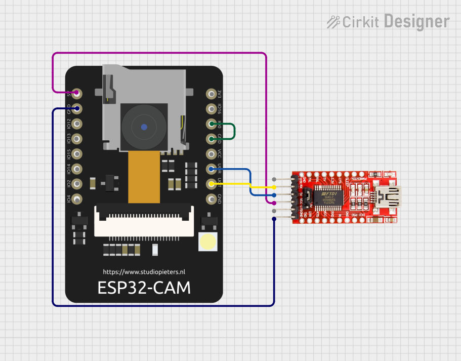
This circuit connects an ESP32 CAM module to an FTDI Programmer for power and serial communication. The ESP32 CAM is programmed to capture images and stream them over WiFi, acting as a web server to provide a live video feed.
ESP32-CAM FTDI Interface for Serial Communication
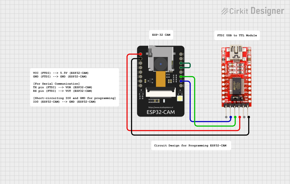
This circuit connects an ESP32-CAM module with an FTDI Programmer for serial communication and programming. The 5V and GND pins of the ESP32-CAM are connected to the VCC and GND of the FTDI to provide power. The TX and RX pins of the ESP32-CAM are connected to the RX and TX pins of the FTDI, respectively, to enable serial data transfer. Additionally, the IO0 pin of the ESP32-CAM is grounded, likely to put the module into flashing mode for programming.
Explore Projects Built with FTDI Programmer
ATMEGA328 Microcontroller Circuit with Serial Programming Interface
This circuit features an ATMEGA328 microcontroller configured with a crystal oscillator for precise timing, and a pushbutton for reset functionality. An FTDI Programmer is connected for serial communication, allowing for programming and data exchange with the microcontroller.
ESP32 CAM Wi-Fi Controlled Camera with FTDI Programmer
This circuit connects an ESP32 CAM module to an FTDI Programmer for programming and communication purposes. The FTDI Programmer provides power and ground to the ESP32 CAM, and the RX/TX lines are connected for serial communication. Additionally, GPIO0 of the ESP32 CAM is grounded to enable programming mode.
ESP32 CAM Wi-Fi Controlled Camera with FTDI Programmer
This circuit connects an ESP32 CAM module to an FTDI Programmer for power and serial communication. The ESP32 CAM is programmed to capture images and stream them over WiFi, acting as a web server to provide a live video feed.
ESP32-CAM FTDI Interface for Serial Communication
This circuit connects an ESP32-CAM module with an FTDI Programmer for serial communication and programming. The 5V and GND pins of the ESP32-CAM are connected to the VCC and GND of the FTDI to provide power. The TX and RX pins of the ESP32-CAM are connected to the RX and TX pins of the FTDI, respectively, to enable serial data transfer. Additionally, the IO0 pin of the ESP32-CAM is grounded, likely to put the module into flashing mode for programming.
Common Applications and Use Cases
- Programming microcontrollers via a serial bootloader
- Providing a USB to Serial interface for debugging and logging
- Communicating with modules and sensors that have a serial interface
- Uploading firmware to devices without a native USB port
Technical Specifications
Key Technical Details
- Voltage Levels: 3.3V or 5V (selectable via jumper or switch)
- Current Rating: Typically 50mA for the FTDI chip itself
- Power Ratings: 500mA from USB port (max)
- Interface: USB to Serial (UART)
- Supported Baud Rates: From 300 baud up to 3 Mbaud
Pin Configuration and Descriptions
| Pin Number | Name | Description |
|---|---|---|
| 1 | GND | Ground connection |
| 2 | CTS | Clear To Send, flow control input signal |
| 3 | VCC | Power supply (3.3V or 5V) |
| 4 | TXD | Transmit Data, outputs data from USB to serial device |
| 5 | RXD | Receive Data, receives data from serial device to USB |
| 6 | RTS | Request To Send, flow control output signal |
| 7 | DTR | Data Terminal Ready, used to reset some microcontrollers |
Usage Instructions
How to Use the Component in a Circuit
Connect the FTDI Programmer to the Target Device:
- Ensure that the voltage levels of the FTDI Programmer match the target device.
- Connect the TXD pin of the FTDI Programmer to the RXD pin of the target device.
- Connect the RXD pin of the FTDI Programmer to the TXD pin of the target device.
- Connect the GND pin of the FTDI Programmer to the GND of the target device.
- Optionally, connect the DTR or RTS pin to reset the target device if required.
Connect the FTDI Programmer to the Computer:
- Use a USB cable to connect the FTDI Programmer to a USB port on the computer.
Install Drivers:
- Install the necessary drivers for the FTDI chip on your computer.
Programming/Communication:
- Use a serial communication program or integrated development environment (IDE) to communicate with the target device.
Important Considerations and Best Practices
- Always verify the voltage level compatibility between the FTDI Programmer and the target device.
- Avoid connecting or disconnecting the FTDI Programmer while the target device is powered to prevent damage.
- Use proper ESD precautions when handling the FTDI Programmer to avoid damaging sensitive components.
Troubleshooting and FAQs
Common Issues Users Might Face
- Driver Installation Problems: Ensure that the correct drivers are installed for the FTDI chip.
- No Communication: Check all connections, including TXD to RXD and vice versa, and ensure proper power supply.
- Incorrect Baud Rate: Verify that the baud rate on the FTDI Programmer matches the target device's settings.
Solutions and Tips for Troubleshooting
- If the device is not recognized, try using a different USB port or cable.
- For driver issues, visit the FTDI website for the latest drivers and installation guides.
- Use loopback tests by connecting TXD to RXD on the FTDI Programmer to check if the module is working correctly.
FAQs
- Q: How do I change the voltage level from 5V to 3.3V?
- A: Use the onboard jumper or switch to select the desired voltage level.
- Q: Can I use the FTDI Programmer with an Arduino?
- A: Yes, the FTDI Programmer can be used to program Arduino boards with a serial bootloader.
Example Code for Arduino UNO
// This example demonstrates how to use the FTDI Programmer to send data
// from a computer to an Arduino UNO's serial port.

void setup() {
  // Initialize serial communication at 9600 baud rate
  Serial.begin(9600);
}

void loop() {
  // Check if data is available to read from the serial port
  if (Serial.available() > 0) {
    // Read the incoming byte
    char incomingByte = Serial.read();

    // Echo the incoming byte back to the serial port
    Serial.write(incomingByte);
  }
}
Remember to select the correct COM port and board configuration in the Arduino IDE when uploading code using an FTDI Programmer.