How to Use AC LED Voltmeter: Examples, Pinouts, and Specs
Introduction
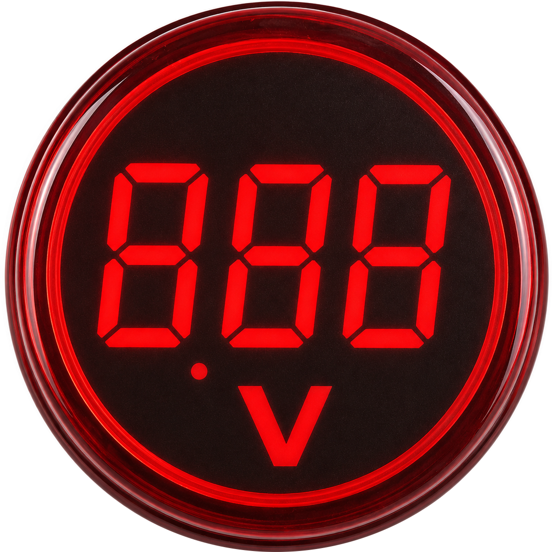
The AC LED Voltmeter is an electronic device designed to measure the voltage of alternating current (AC) circuits. Manufactured by Generic, this voltmeter features an LED display that provides a clear and easy-to-read output, making it ideal for monitoring electrical systems. Its compact design and straightforward operation make it a popular choice for both hobbyists and professionals.
Explore Projects Built with AC LED Voltmeter
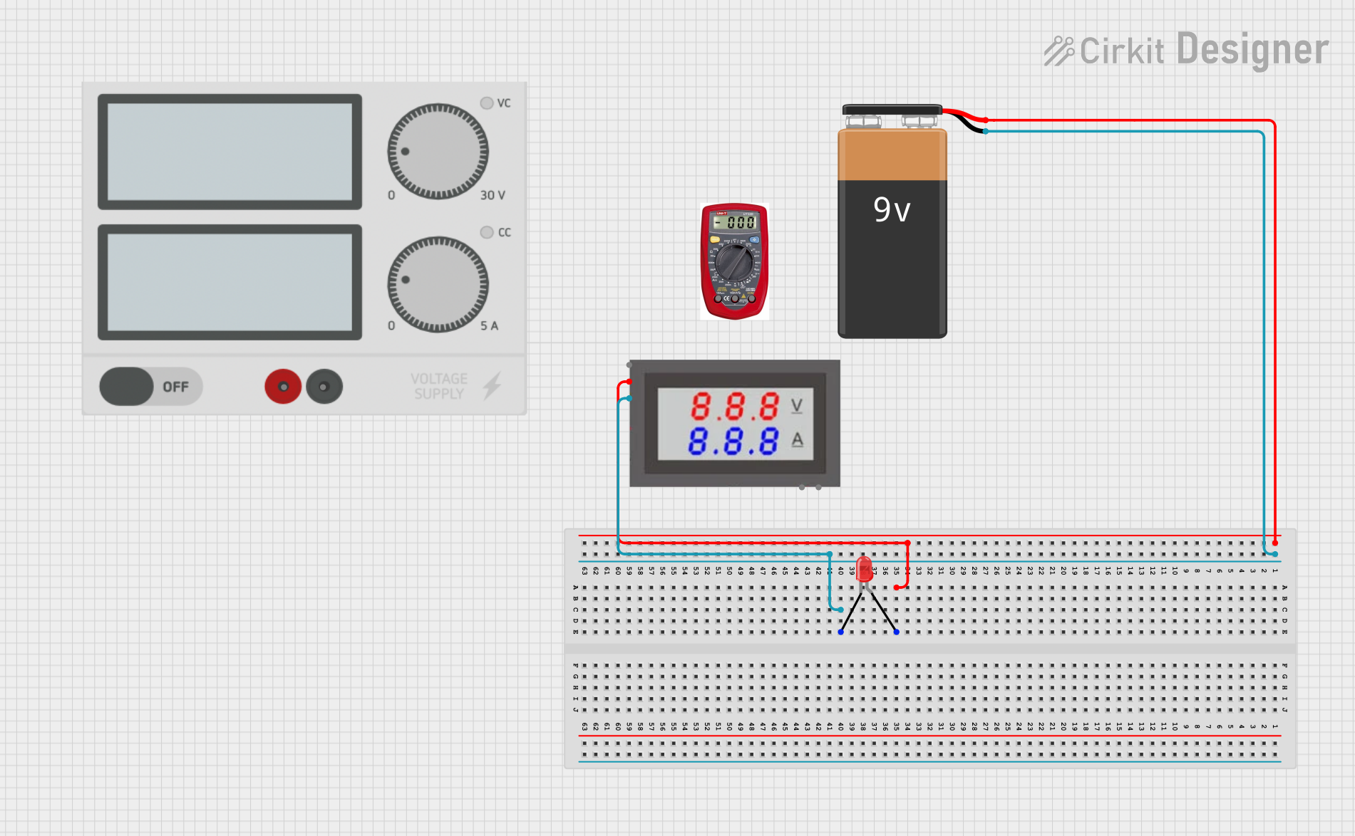
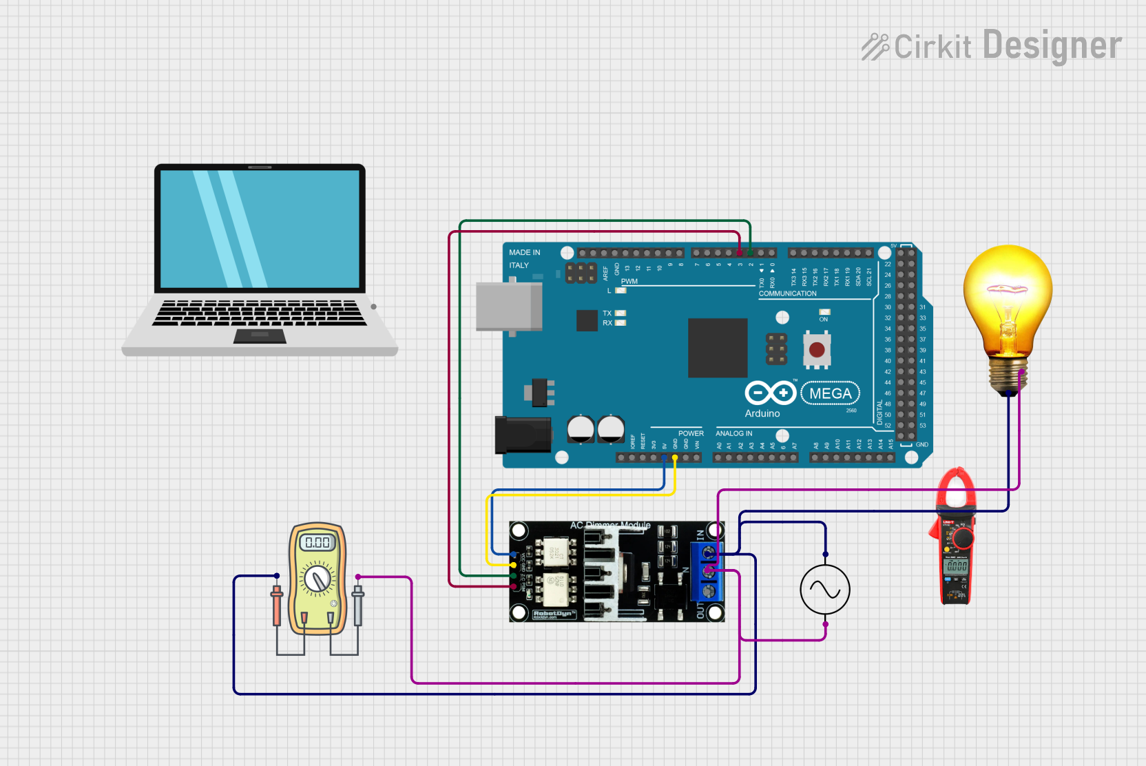
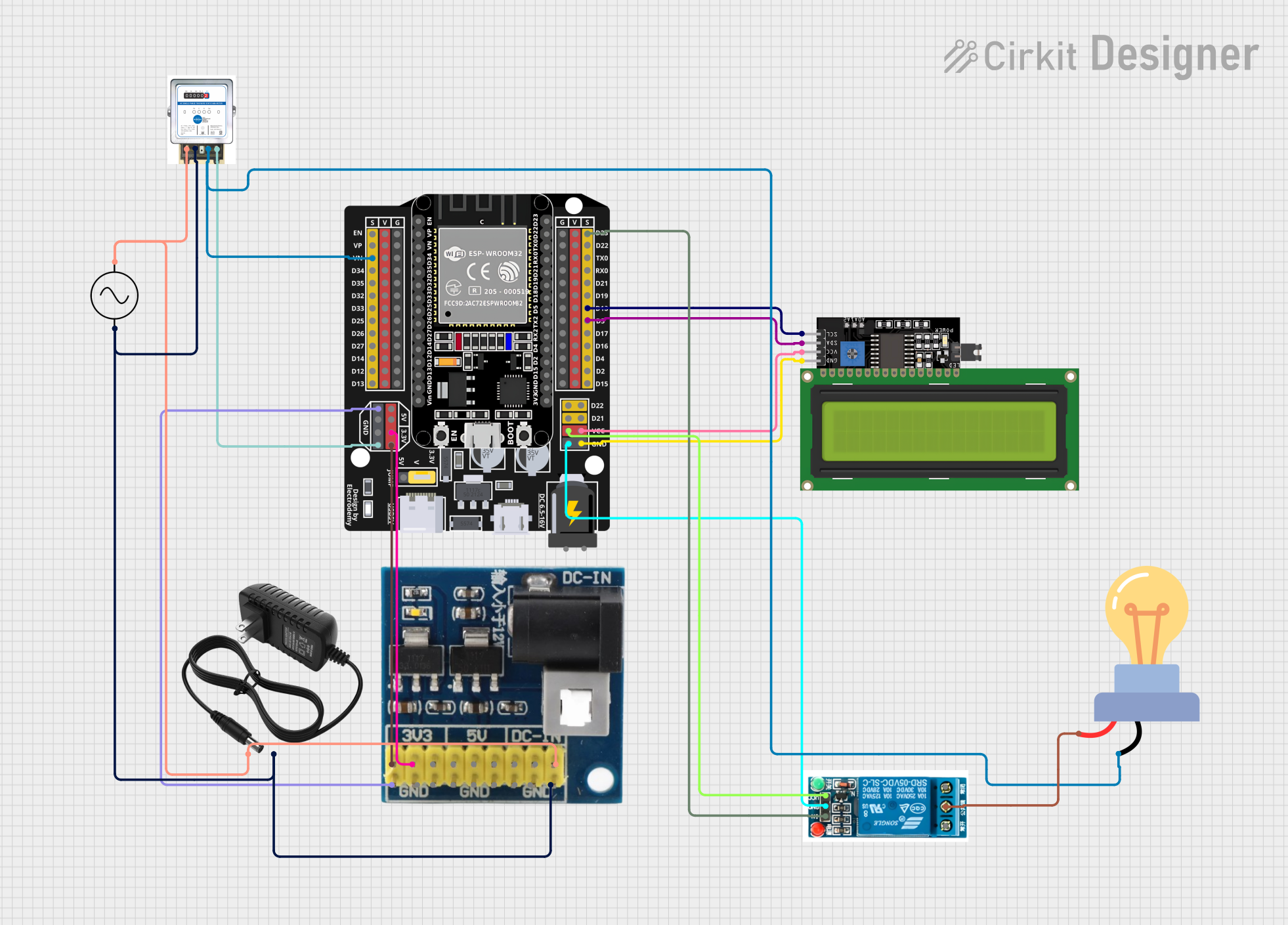

Explore Projects Built with AC LED Voltmeter
Common Applications and Use Cases
- Monitoring AC voltage in household or industrial electrical systems.
- Testing and troubleshooting AC-powered devices.
- Integrating into power distribution panels for real-time voltage monitoring.
- Educational purposes in electronics labs and training setups.
Technical Specifications
The following table outlines the key technical details of the AC LED Voltmeter:
| Parameter | Specification |
|---|---|
| Operating Voltage | 80V AC to 300V AC |
| Display Type | 3-digit LED display |
| Measurement Accuracy | ±1% |
| Power Consumption | < 0.5W |
| Display Color | Red, Green, or Blue (varies by model) |
| Refresh Rate | 2-3 readings per second |
| Dimensions | 48mm x 29mm x 21mm |
| Mounting Type | Panel mount |
Pin Configuration and Descriptions
The AC LED Voltmeter typically has two input terminals for connection. The table below describes the terminals:
| Pin/Terminal | Description |
|---|---|
| AC Input (L) | Live wire connection for AC voltage input |
| AC Input (N) | Neutral wire connection for AC voltage |
Note: Ensure proper polarity when connecting the voltmeter to avoid incorrect readings or damage.
Usage Instructions
How to Use the Component in a Circuit
- Power Off the Circuit: Before connecting the voltmeter, ensure the circuit is powered off to avoid electrical hazards.
- Connect the Terminals:
- Connect the AC Input (L) terminal to the live wire of the AC circuit.
- Connect the AC Input (N) terminal to the neutral wire of the AC circuit.
- Secure the Voltmeter: Mount the voltmeter securely in a panel or enclosure using the provided mounting slots.
- Power On the Circuit: Once the connections are secure, power on the circuit. The LED display will show the measured AC voltage in real-time.
Important Considerations and Best Practices
- Voltage Range: Ensure the AC voltage being measured is within the specified range (80V AC to 300V AC). Exceeding this range may damage the voltmeter.
- Isolation: Avoid direct contact with live wires during installation. Use insulated tools and follow safety protocols.
- Environmental Conditions: Operate the voltmeter in a dry and dust-free environment to ensure accurate readings and longevity.
- Calibration: If the voltmeter readings appear inaccurate, consider recalibrating it using a reference voltage source.
Arduino Integration
While the AC LED Voltmeter is not directly programmable, it can be used alongside an Arduino UNO for monitoring purposes. For example, you can use an optocoupler or voltage sensor module to interface the AC voltage readings with the Arduino. Below is an example code snippet for reading and displaying voltage using an Arduino and a compatible voltage sensor module:
// Example code for reading AC voltage using an Arduino and a voltage sensor module
const int sensorPin = A0;  // Analog pin connected to the voltage sensor
float calibrationFactor = 11.0; // Adjust based on your sensor's specifications

void setup() {
  Serial.begin(9600); // Initialize serial communication
}

void loop() {
  int sensorValue = analogRead(sensorPin); // Read the analog value from the sensor
  float voltage = (sensorValue / 1023.0) * 5.0 * calibrationFactor;

  // Print the voltage to the Serial Monitor
  Serial.print("AC Voltage: ");
  Serial.print(voltage);
  Serial.println(" V");

  delay(1000); // Wait for 1 second before the next reading
}
Note: The above code assumes the use of a voltage sensor module that steps down the AC voltage to a safe level for the Arduino. Directly connecting the AC LED Voltmeter to an Arduino is not recommended.
Troubleshooting and FAQs
Common Issues and Solutions
| Issue | Possible Cause | Solution |
|---|---|---|
| No display on the LED screen | Loose or incorrect wiring | Check and secure all connections. |
| Incorrect voltage readings | Voltage outside the specified range | Ensure the input voltage is within 80-300V AC. |
| Flickering or unstable display | Electrical noise or interference | Use proper shielding and grounding. |
| Voltmeter not powering on | Faulty device or insufficient input voltage | Verify the input voltage and replace if necessary. |
Frequently Asked Questions
Can this voltmeter measure DC voltage?
- No, the AC LED Voltmeter is designed specifically for AC voltage measurement.
What happens if the input voltage exceeds 300V AC?
- Exceeding the voltage range may damage the voltmeter. Always ensure the input voltage is within the specified range.
Can I use this voltmeter outdoors?
- The voltmeter is not weatherproof. Use it in a dry, indoor environment or within a weatherproof enclosure.
How do I clean the LED display?
- Use a soft, dry cloth to clean the display. Avoid using water or cleaning agents.
By following this documentation, users can effectively utilize the AC LED Voltmeter for accurate and reliable AC voltage measurements.