How to Use БК-24-RS485-01: Examples, Pinouts, and Specs
Introduction
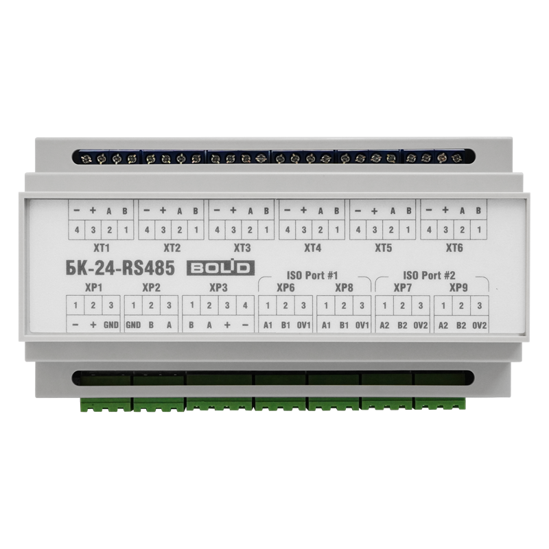
The БК-24-RS485-01 is a robust communication module manufactured by Bolid, designed for RS-485 serial communication. It facilitates reliable and efficient data transmission over long distances, making it ideal for industrial and commercial applications. The module supports multi-device communication on a single bus, adhering to the RS-485 standard, which ensures noise immunity and differential signaling for enhanced reliability.
Explore Projects Built with БК-24-RS485-01


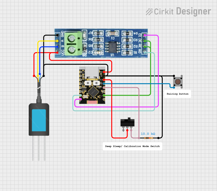
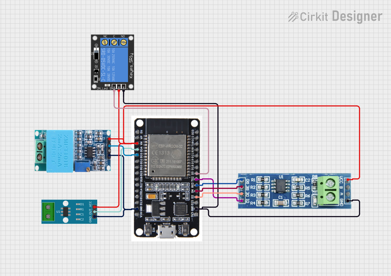
Explore Projects Built with БК-24-RS485-01
Common Applications and Use Cases
- Industrial automation and control systems
- Building management systems (BMS)
- Security and fire alarm systems
- Data acquisition and monitoring
- Communication between microcontrollers and PLCs
- Long-distance serial communication in noisy environments
Technical Specifications
Key Technical Details
| Parameter | Specification |
|---|---|
| Communication Standard | RS-485 |
| Supply Voltage | 24V DC ± 10% |
| Power Consumption | ≤ 1.5 W |
| Baud Rate | Up to 115.2 kbps |
| Maximum Bus Length | 1200 meters (at 9600 bps) |
| Maximum Devices on Bus | 32 devices |
| Operating Temperature Range | -40°C to +70°C |
| Dimensions | 90mm x 60mm x 25mm |
| Mounting | DIN rail or surface mount |
Pin Configuration and Descriptions
| Pin Number | Pin Name | Description |
|---|---|---|
| 1 | A (Data+) | RS-485 differential data line (positive) |
| 2 | B (Data-) | RS-485 differential data line (negative) |
| 3 | GND | Ground connection |
| 4 | V+ | 24V DC power input |
| 5 | Shield | Shielding for noise protection |
Usage Instructions
How to Use the БК-24-RS485-01 in a Circuit
- Power Supply: Connect the V+ pin to a regulated 24V DC power source and the GND pin to the ground of the power supply.
- RS-485 Bus Connection:
- Connect the A (Data+) and B (Data-) pins to the corresponding lines of the RS-485 bus.
- Use twisted-pair cables for the A and B lines to minimize noise and signal degradation.
- Shielding: Connect the Shield pin to the cable shield or ground to improve noise immunity.
- Termination Resistor: If the module is at the end of the RS-485 bus, add a 120-ohm termination resistor between the A and B lines to prevent signal reflections.
- Device Addressing: Ensure each device on the RS-485 bus has a unique address to avoid communication conflicts.
Important Considerations and Best Practices
- Cable Selection: Use high-quality, twisted-pair cables with shielding for long-distance communication.
- Grounding: Properly ground the module to prevent ground loops and ensure stable operation.
- Baud Rate: Match the baud rate of all devices on the RS-485 bus for successful communication.
- Device Count: Do not exceed the maximum of 32 devices on a single RS-485 bus without using repeaters.
- Electrostatic Discharge (ESD) Protection: Handle the module with care to avoid damage from ESD.
Example: Connecting to an Arduino UNO
The БК-24-RS485-01 can be used with an Arduino UNO for RS-485 communication. Below is an example of how to connect and program the module:
Wiring Diagram
| Arduino UNO Pin | БК-24-RS485-01 Pin |
|---|---|
| GND | GND |
| 5V | V+ (via a 5V to 24V DC converter) |
| D2 (TX) | A (Data+) |
| D3 (RX) | B (Data-) |
Arduino Code Example
#include <SoftwareSerial.h>

// Define RS-485 communication pins
#define RX_PIN 3  // Arduino pin connected to RS-485 Data- (B)
#define TX_PIN 2  // Arduino pin connected to RS-485 Data+ (A)

// Initialize SoftwareSerial for RS-485 communication
SoftwareSerial rs485Serial(RX_PIN, TX_PIN);

void setup() {
  // Start serial communication for debugging
  Serial.begin(9600);
  Serial.println("RS-485 Communication Test");

  // Start RS-485 communication
  rs485Serial.begin(9600);
}

void loop() {
  // Send data over RS-485
  rs485Serial.println("Hello from Arduino!");

  // Check if data is available to read
  if (rs485Serial.available()) {
    String receivedData = rs485Serial.readString();
    Serial.print("Received: ");
    Serial.println(receivedData);
  }

  delay(1000); // Wait for 1 second
}
Troubleshooting and FAQs
Common Issues and Solutions
No Communication Between Devices
- Cause: Incorrect wiring or mismatched baud rates.
- Solution: Verify the A and B lines are correctly connected and ensure all devices use the same baud rate.
Signal Degradation Over Long Distances
- Cause: Poor-quality cables or lack of termination resistors.
- Solution: Use high-quality, twisted-pair cables and add 120-ohm termination resistors at both ends of the RS-485 bus.
Interference or Noise in Communication
- Cause: Improper shielding or grounding.
- Solution: Ensure the Shield pin is connected to the cable shield or ground.
Overheating of the Module
- Cause: Exceeding the power supply voltage or improper ventilation.
- Solution: Use a regulated 24V DC power supply and ensure adequate airflow around the module.
FAQs
Q1: Can the БК-24-RS485-01 be used outdoors?
A1: The module is designed for industrial environments but should be housed in a weatherproof enclosure for outdoor use.
Q2: How many devices can I connect to a single RS-485 bus?
A2: The module supports up to 32 devices on a single bus. For more devices, use RS-485 repeaters.
Q3: What is the maximum communication distance?
A3: The maximum distance is 1200 meters at a baud rate of 9600 bps. Higher baud rates may reduce the effective distance.
Q4: Is the module compatible with 5V microcontrollers?
A4: Yes, but you will need a 5V to 24V DC converter for the power supply. Ensure proper voltage level shifting for data lines if required.