
How to Use 7-SEGMENT-4DIGIT: Examples, Pinouts, and Specs
 Design with 7-SEGMENT-4DIGIT in Cirkit Designer
Introduction
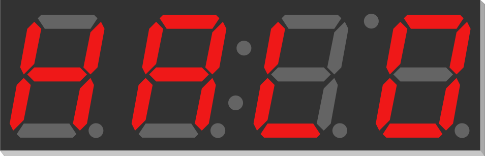
The 7-SEGMENT-4DIGIT display is a versatile electronic component designed to visually represent decimal numbers. It consists of four individual seven-segment digits, each made up of seven LEDs (segments) arranged in a figure-eight pattern. By illuminating specific segments, the display can represent numbers from 0 to 9 on each digit.
This component is widely used in digital clocks, counters, timers, and other devices requiring numeric displays. Its compact design and ease of use make it a popular choice for both hobbyists and professionals.
Explore Projects Built with 7-SEGMENT-4DIGIT
 Open Project in Cirkit Designer
 Open Project in Cirkit Designer
 Open Project in Cirkit Designer
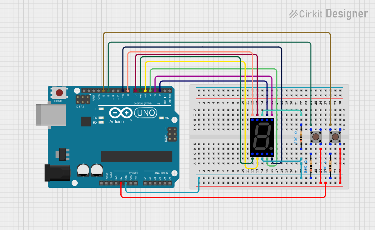 Open Project in Cirkit Designer
Explore Projects Built with 7-SEGMENT-4DIGIT
Open Project in Cirkit DesignerOpen Project in Cirkit DesignerOpen Project in Cirkit DesignerOpen Project in Cirkit DesignerTechnical Specifications
- Type: 4-digit seven-segment display
- Operating Voltage: Typically 3.3V to 5V (check specific model datasheet)
- Current Consumption: ~20mA per segment (varies by model)
- Display Type: Common Cathode or Common Anode (varies by model)
- Number of Pins: 12 to 16 (depending on configuration)
- Digit Height: Typically 0.36" to 1.0" (varies by model)
- Segment Color: Red (common), Green, Blue, or other colors depending on the model
- Viewing Angle: ~120 degrees
Pin Configuration and Descriptions
The pin configuration of a 7-SEGMENT-4DIGIT display depends on whether it is a Common Cathode or Common Anode type. Below is a general pinout for a 12-pin Common Cathode display:
| Pin Number | Description |
|---|---|
| 1 | Segment 'e' of Digit 4 |
| 2 | Segment 'd' of Digit 4 |
| 3 | Common Cathode for Digit 4 |
| 4 | Segment 'c' of Digit 4 |
| 5 | Segment 'g' of Digit 4 |
| 6 | Segment 'b' of Digit 4 |
| 7 | Segment 'a' of Digit 4 |
| 8 | Common Cathode for Digit 3 |
| 9 | Segment 'f' of Digit 4 |
| 10 | Segment 'e' of Digit 3 |
| 11 | Segment 'd' of Digit 3 |
| 12 | Common Cathode for Digit 2 |
For a Common Anode display, the cathode and anode roles are reversed.
Usage Instructions
How to Use the Component in a Circuit
- Determine the Type: Identify whether your display is Common Cathode or Common Anode. This information is crucial for proper wiring.
- Connect the Pins:
- For a Common Cathode display, connect the cathode pins (common pins) to ground.
- For a Common Anode display, connect the anode pins (common pins) to the positive voltage supply.
- Control the Segments: Use current-limiting resistors (typically 220Ω to 1kΩ) to connect each segment pin to a microcontroller or driver IC. This prevents excessive current from damaging the LEDs.
- Multiplexing: To control all four digits with fewer pins, use a multiplexing technique. Activate one digit at a time while controlling the segments to display the desired number.
Important Considerations and Best Practices
- Resistors: Always use appropriate resistors to limit current through the segments.
- Brightness Control: Use Pulse Width Modulation (PWM) to adjust the brightness of the display.
- Driver ICs: For easier control, consider using a driver IC like the MAX7219 or TM1637, which simplifies multiplexing and reduces the number of required microcontroller pins.
- Power Supply: Ensure your power supply can handle the total current draw of the display.
Example: Connecting to an Arduino UNO
Below is an example of how to connect and control a 7-SEGMENT-4DIGIT display using an Arduino UNO and the TM1637 driver module:
Circuit Connections
- Connect the CLK pin of the TM1637 module to Arduino pin D2.
- Connect the DIO pin of the TM1637 module to Arduino pin D3.
- Connect the VCC pin of the TM1637 module to the 5V pin on the Arduino.
- Connect the GND pin of the TM1637 module to the GND pin on the Arduino.
Arduino Code
#include <TM1637Display.h> // Include the TM1637 library

#define CLK 2  // Define the clock pin
#define DIO 3  // Define the data pin

TM1637Display display(CLK, DIO); // Initialize the display object

void setup() {
  display.setBrightness(7); // Set brightness (0 to 7)
}

void loop() {
  for (int i = 0; i <= 9999; i++) {
    display.showNumberDec(i, false); // Display the number
    delay(500); // Wait for 500ms
  }
}
Troubleshooting and FAQs
Common Issues
Segments Not Lighting Up:
- Check the wiring and ensure all connections are secure.
- Verify that the correct resistors are used to limit current.
- Ensure the power supply voltage matches the display's requirements.
Incorrect Digits Displayed:
- Double-check the pin connections to ensure they match the segment mapping.
- Verify the type of display (Common Cathode or Common Anode) and adjust the circuit accordingly.
Flickering Display:
- This may occur if multiplexing is not implemented correctly. Ensure that only one digit is activated at a time.
- Use a driver IC like the MAX7219 or TM1637 to simplify multiplexing.
FAQs
Q: Can I use the 7-SEGMENT-4DIGIT display without a driver IC?
A: Yes, but you will need to manually implement multiplexing in your code, which can be complex and requires more microcontroller pins.
Q: How do I control the brightness of the display?
A: Brightness can be controlled using PWM or by adjusting the current-limiting resistors. If using a driver IC like the TM1637, you can set the brightness programmatically.
Q: Can I display letters on the 7-SEGMENT-4DIGIT display?
A: Some letters (e.g., A, b, C, d, E, F) can be displayed by illuminating specific segments, but the display is primarily designed for numbers.
By following this documentation, you can effectively integrate and troubleshoot the 7-SEGMENT-4DIGIT display in your projects.