
How to Use Matek AP_Periph CAN Digital Power Monitor, CAN-L4-BM: Examples, Pinouts, and Specs
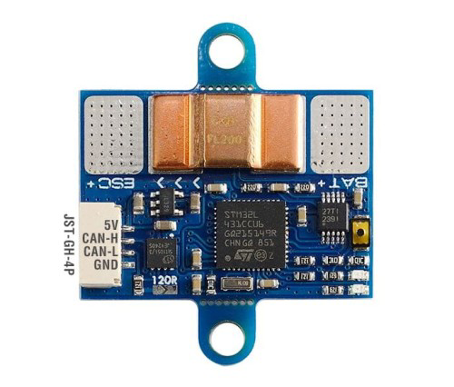
 Design with Matek AP_Periph CAN Digital Power Monitor, CAN-L4-BM in Cirkit Designer
Introduction
The Matek AP_Periph CAN Digital Power Monitor (Model: CAN-L4-BM) is a high-precision power monitoring module designed for use in UAVs, robotics, and other embedded systems. It leverages the UAVCAN protocol for seamless integration with modern flight controllers and other CAN-enabled devices. This module provides real-time monitoring of voltage, current, and power consumption, making it an essential component for applications requiring accurate power management and telemetry.
Explore Projects Built with Matek AP_Periph CAN Digital Power Monitor, CAN-L4-BM
 Open Project in Cirkit Designer
 Open Project in Cirkit Designer
 Open Project in Cirkit Designer
 Open Project in Cirkit Designer
Explore Projects Built with Matek AP_Periph CAN Digital Power Monitor, CAN-L4-BM
Open Project in Cirkit DesignerOpen Project in Cirkit DesignerOpen Project in Cirkit DesignerOpen Project in Cirkit DesignerCommon Applications and Use Cases
- UAVs and drones for power monitoring and telemetry
- Robotics systems requiring precise energy management
- Remote monitoring of battery performance in embedded systems
- Integration with UAVCAN-enabled flight controllers for advanced power diagnostics
Technical Specifications
The following table outlines the key technical specifications of the Matek AP_Periph CAN Digital Power Monitor:
| Parameter | Value |
|---|---|
| Input Voltage Range | 6V to 60V |
| Current Measurement Range | 0A to 200A (with external shunt resistor) |
| Communication Protocol | UAVCAN (CAN bus) |
| Microcontroller | STM32L4 series |
| Power Consumption | < 0.5W |
| Operating Temperature | -20°C to 85°C |
| Dimensions | 30mm x 20mm x 5mm |
| Weight | 5g |
Pin Configuration and Descriptions
The Matek AP_Periph CAN Digital Power Monitor features the following pinout:
| Pin Name | Description |
|---|---|
| VIN+ | Positive input voltage terminal (connect to battery +) |
| VIN- | Negative input voltage terminal (connect to battery -) |
| CANH | CAN bus high signal |
| CANL | CAN bus low signal |
| GND | Ground connection |
| VCC | Power supply for the module (5V input) |
Usage Instructions
How to Use the Component in a Circuit
- Power Connection: Connect the VIN+ and VIN- terminals to the positive and negative terminals of the power source (e.g., battery). Ensure the voltage is within the specified range (6V to 60V).
- CAN Bus Connection: Connect the CANH and CANL pins to the corresponding CAN bus lines of your system. Use a 120-ohm termination resistor if the module is at the end of the CAN bus.
- Power Supply: Provide a stable 5V power supply to the VCC pin. Ensure the GND pin is connected to the system ground.
- Shunt Resistor: If measuring high currents, connect an appropriate external shunt resistor to the module. Ensure the shunt resistor is rated for the expected current range.
Important Considerations and Best Practices
- UAVCAN Configuration: Configure the module's UAVCAN parameters (e.g., node ID) using a compatible UAVCAN configuration tool.
- Wiring: Use short, thick wires for the VIN+ and VIN- connections to minimize voltage drops and ensure accurate measurements.
- Calibration: Calibrate the module using the UAVCAN tool to ensure precise voltage and current readings.
- Firmware Updates: Periodically check for firmware updates from Mateksys to ensure compatibility with the latest UAVCAN standards.
Example Code for Arduino UNO (via CAN Interface)
To interface the Matek AP_Periph CAN Digital Power Monitor with an Arduino UNO, you will need a CAN transceiver module (e.g., MCP2515). Below is an example code snippet:
#include <SPI.h>
#include <mcp_can.h>

// Define CAN bus pins for MCP2515
#define CAN_CS 10  // Chip Select pin
#define CAN_INT 2  // Interrupt pin

MCP_CAN CAN(CAN_CS);  // Create CAN object

void setup() {
  Serial.begin(115200);
  while (!Serial);

  // Initialize MCP2515 CAN module at 500kbps
  if (CAN.begin(MCP_ANY, 500000, MCP_8MHZ) == CAN_OK) {
    Serial.println("CAN bus initialized successfully!");
  } else {
    Serial.println("CAN bus initialization failed!");
    while (1);
  }

  CAN.setMode(MCP_NORMAL);  // Set CAN module to normal mode
  Serial.println("CAN module set to normal mode.");
}

void loop() {
  // Check for incoming CAN messages
  if (CAN.checkReceive() == CAN_MSGAVAIL) {
    long unsigned int rxId;
    unsigned char len = 0;
    unsigned char rxBuf[8];

    // Read CAN message
    CAN.readMsgBuf(&rxId, &len, rxBuf);

    // Print received message ID and data
    Serial.print("Message ID: 0x");
    Serial.println(rxId, HEX);
    Serial.print("Data: ");
    for (int i = 0; i < len; i++) {
      Serial.print(rxBuf[i], HEX);
      Serial.print(" ");
    }
    Serial.println();
  }
}
Note: Ensure the MCP2515 library is installed in your Arduino IDE. This code initializes the CAN bus and listens for incoming messages from the Matek AP_Periph CAN Digital Power Monitor.
Troubleshooting and FAQs
Common Issues Users Might Face
No Data on CAN Bus:
- Cause: Incorrect wiring or missing termination resistor.
- Solution: Verify the CANH and CANL connections. Add a 120-ohm resistor if the module is at the end of the CAN bus.
Inaccurate Measurements:
- Cause: Improper calibration or incorrect shunt resistor value.
- Solution: Recalibrate the module using the UAVCAN tool. Ensure the shunt resistor matches the expected current range.
Module Not Powering On:
- Cause: Insufficient or unstable power supply.
- Solution: Check the VCC and GND connections. Ensure a stable 5V supply is provided.
Solutions and Tips for Troubleshooting
- Use a CAN bus analyzer to verify communication between the module and the flight controller.
- Check for firmware updates from Mateksys to resolve compatibility issues.
- Ensure all connections are secure and free from corrosion or damage.
By following this documentation, users can effectively integrate and utilize the Matek AP_Periph CAN Digital Power Monitor in their projects.