How to Use Placa: Examples, Pinouts, and Specs
Introduction
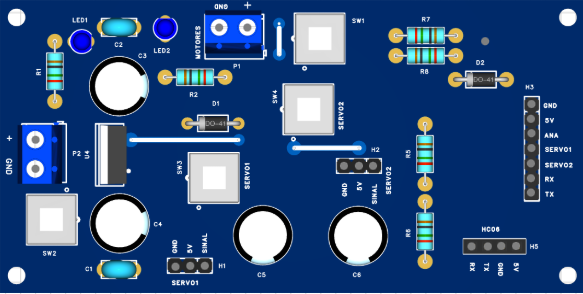
The Placa, commonly referred to as a circuit board, is a foundational electronic component that provides a platform for mounting and interconnecting various electronic components. It serves as the backbone of most electronic devices, enabling the integration of resistors, capacitors, microcontrollers, and other components into a cohesive circuit.
Placas are available in various forms, such as printed circuit boards (PCBs), breadboards, and prototyping boards, each suited for specific applications. They are widely used in prototyping, product development, and mass production of electronic devices.
Explore Projects Built with Placa
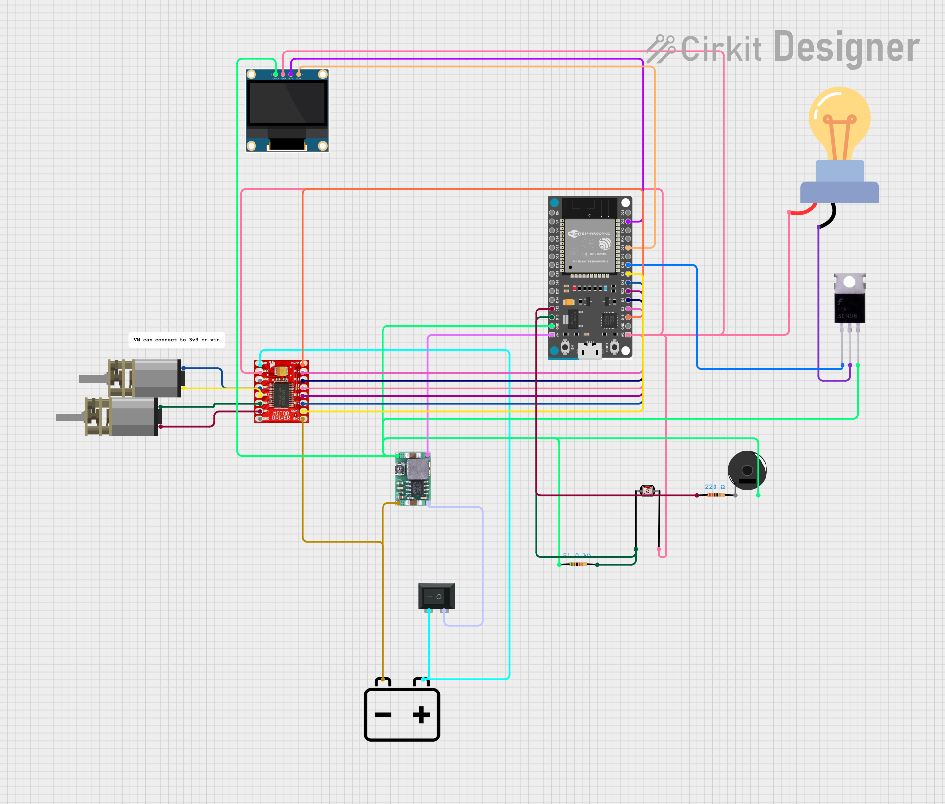
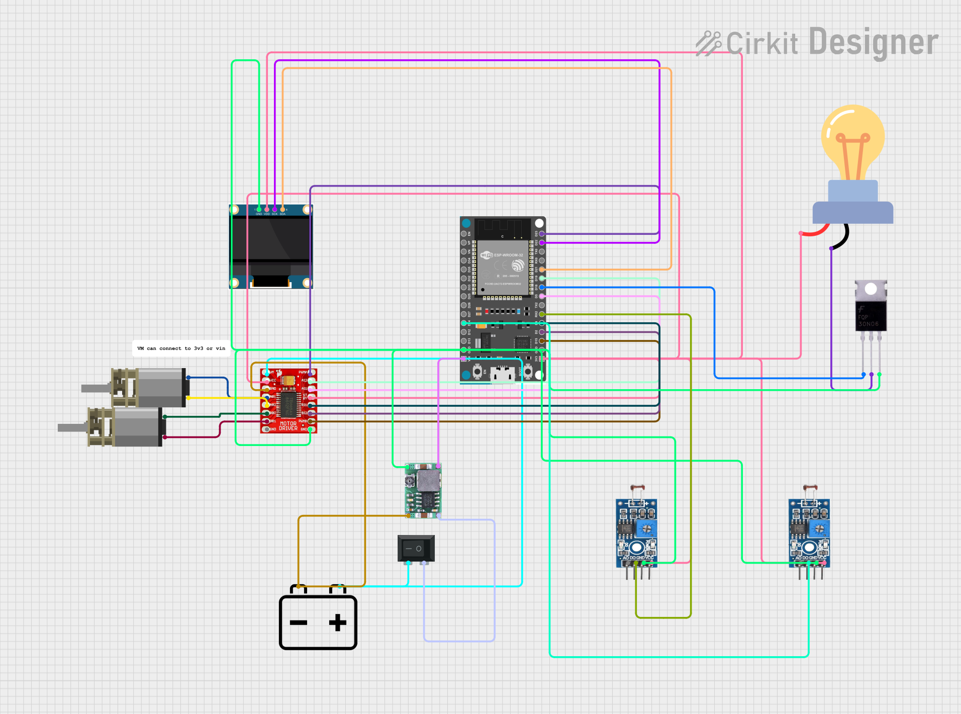
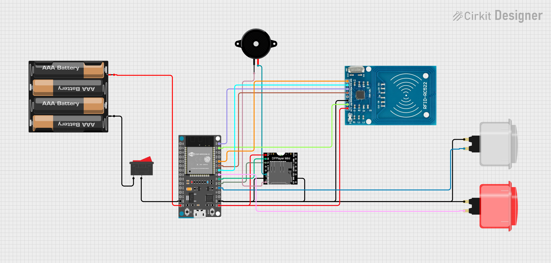
Explore Projects Built with Placa
Common Applications and Use Cases
- Prototyping and testing electronic circuits
- Building custom electronic devices
- Educational purposes for learning circuit design
- Mass production of consumer electronics
- Repair and replacement of damaged circuit boards
Technical Specifications
The specifications of a Placa can vary depending on its type (e.g., breadboard, PCB). Below are general specifications for a standard PCB:
General Specifications
| Parameter | Value/Description |
|---|---|
| Material | FR4 (fiberglass), phenolic, or other substrates |
| Layers | Single-layer, double-layer, or multi-layer |
| Copper Thickness | 1 oz/ft² (35 µm) standard; customizable |
| Board Thickness | 1.6 mm (standard); varies based on application |
| Solder Mask Color | Green (standard); other colors available |
| Surface Finish | HASL, ENIG, OSP, or other finishes |
| Operating Temperature | -40°C to 85°C (typical); varies by material |
Pin Configuration and Descriptions
For breadboards or prototyping boards, the "pins" refer to the connection points or rows. Below is a table describing the layout of a standard breadboard:
| Section | Description |
|---|---|
| Power Rails | Horizontal rows for power (Vcc) and ground (GND) |
| Terminal Strips | Vertical columns for component connections |
| Gap/Divider | Central gap for IC placement |
| Binding Posts (optional) | External power supply connection points |
For PCBs, the pin configuration depends on the specific design and layout of the board.
Usage Instructions
How to Use the Placa in a Circuit
Breadboard (Prototyping):
- Insert components into the terminal strips.
- Use jumper wires to connect components as per the circuit diagram.
- Connect power and ground to the designated power rails.
PCB:
- Design the circuit layout using PCB design software (e.g., KiCad, Eagle).
- Manufacture the PCB or use a pre-fabricated one.
- Solder components onto the board following the design.
General Tips:
- Ensure proper insulation to avoid short circuits.
- Use appropriate tools, such as a soldering iron, multimeter, and wire cutters.
- Verify connections before powering the circuit.
Important Considerations and Best Practices
For Breadboards:
- Avoid high-current applications, as breadboards are not designed for heavy loads.
- Keep wires short and organized to minimize noise and interference.
For PCBs:
- Use proper grounding techniques to reduce electromagnetic interference (EMI).
- Ensure trace widths are adequate for the current they will carry.
- Double-check the polarity of components like diodes and capacitors before soldering.
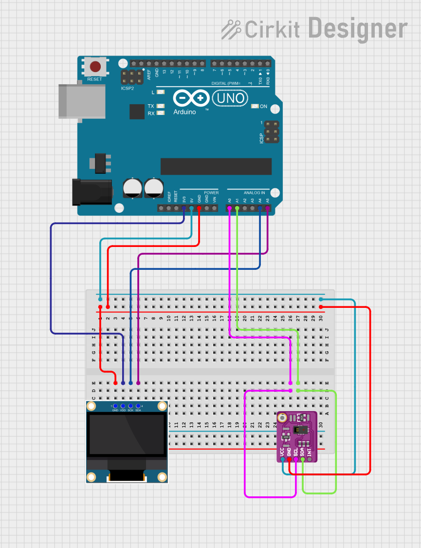
Example: Connecting an LED to an Arduino UNO
Below is an example of using a breadboard to connect an LED to an Arduino UNO:
// Example: Blink an LED using Arduino UNO
// Connect the LED's anode (long leg) to pin 13 via a 220-ohm resistor.
// Connect the LED's cathode (short leg) to GND.

void setup() {
  pinMode(13, OUTPUT); // Set pin 13 as an output
}

void loop() {
  digitalWrite(13, HIGH); // Turn the LED on
  delay(1000);            // Wait for 1 second
  digitalWrite(13, LOW);  // Turn the LED off
  delay(1000);            // Wait for 1 second
}
Troubleshooting and FAQs
Common Issues Users Might Face
Loose Connections:
- Problem: Components or wires are not securely connected.
- Solution: Ensure all connections are tight and properly seated.
Short Circuits:
- Problem: Adjacent pins or traces are accidentally connected.
- Solution: Inspect the board for solder bridges or misplaced wires.
Overheating Components:
- Problem: Components heat up excessively during operation.
- Solution: Verify the circuit design and ensure components are within their rated limits.
PCB Design Errors:
- Problem: Incorrect trace routing or missing connections.
- Solution: Double-check the PCB design before manufacturing.
FAQs
Q: Can I reuse a breadboard for multiple projects?
A: Yes, breadboards are reusable. Simply remove the components and wires after completing a project.
Q: What software should I use for PCB design?
A: Popular options include KiCad, Eagle, Altium Designer, and EasyEDA.
Q: How do I clean a PCB after soldering?
A: Use isopropyl alcohol and a soft brush to remove flux residue and dirt.
Q: Can I use a breadboard for high-frequency circuits?
A: Breadboards are not ideal for high-frequency circuits due to parasitic capacitance and inductance. Use a PCB for such applications.