How to Use N20 motor/Hall sensor: Examples, Pinouts, and Specs
Introduction
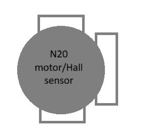
The N20 motor with a Hall sensor is a compact, high-performance DC motor equipped with an integrated Hall-effect sensor for precise speed and position feedback. This motor is widely used in robotics, automation systems, and small-scale mechatronics projects due to its small size, efficiency, and ability to provide real-time feedback.
Explore Projects Built with N20 motor/Hall sensor
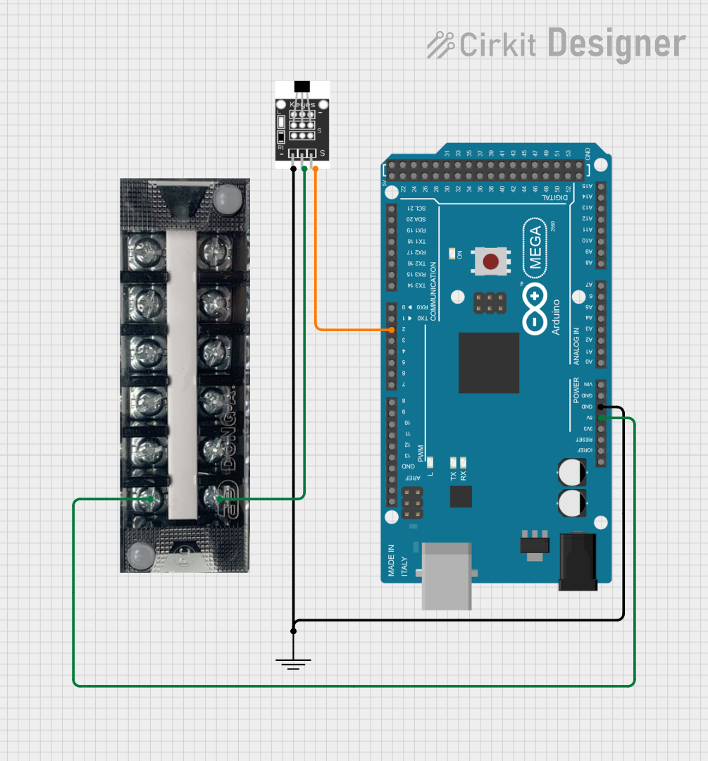
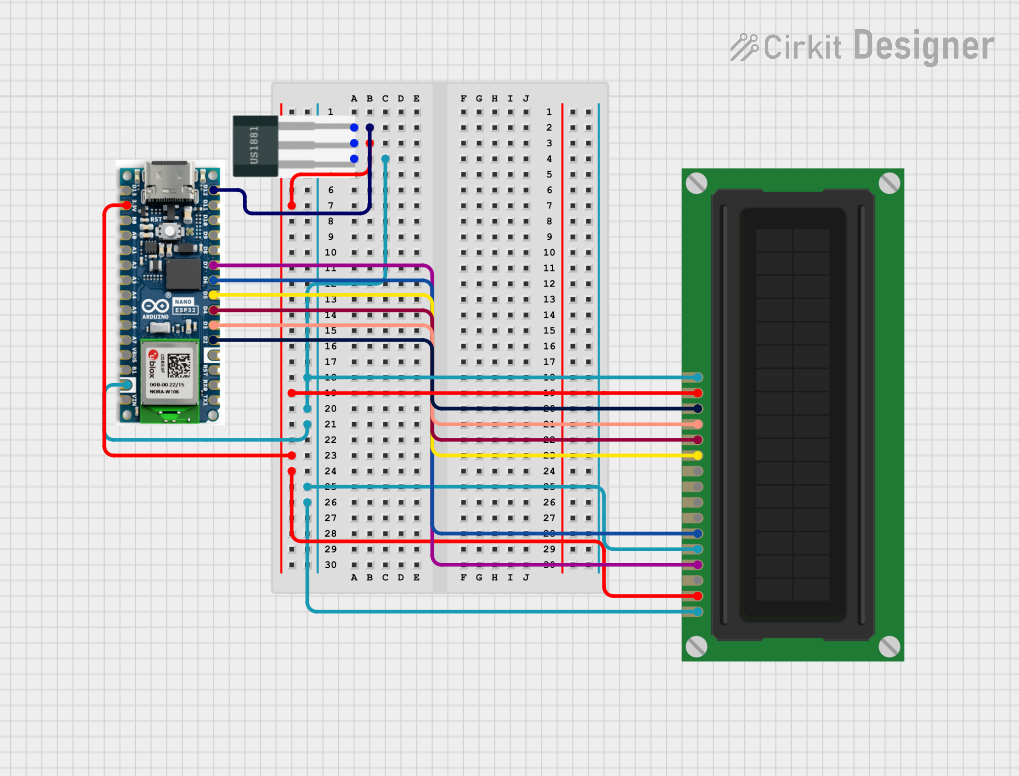
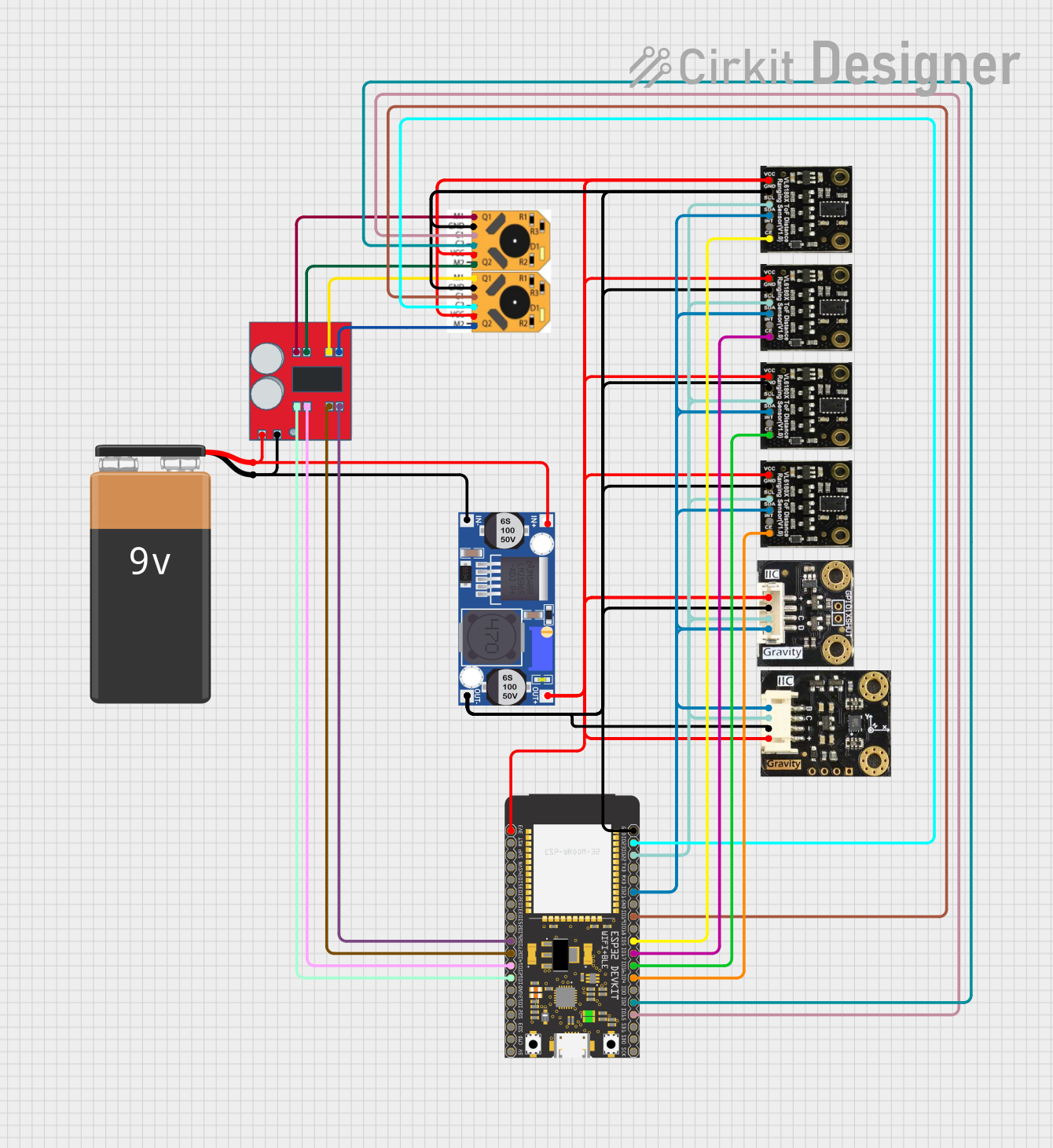
Explore Projects Built with N20 motor/Hall sensor
Common Applications
- Robotic arms and mobile robots
- Automated door locks and mechanisms
- Precision control systems
- Educational and DIY electronics projects
- Encoder-based motor control for speed and position monitoring
Technical Specifications
Motor Specifications
| Parameter | Value |
|---|---|
| Operating Voltage | 3V to 12V |
| Rated Voltage | 6V |
| No-Load Speed | 30 to 1000 RPM (varies by model) |
| Stall Current | ~1.2A (at 6V) |
| Gear Ratio | 1:10 to 1:1000 (varies by model) |
| Shaft Diameter | 3mm |
| Motor Dimensions | 12mm x 10mm x 15mm |
Hall Sensor Specifications
| Parameter | Value |
|---|---|
| Sensor Type | Hall-effect |
| Output Signal | Digital (Square Wave) |
| Operating Voltage | 3.3V to 5V |
| Pulses per Revolution | 2 pulses per motor shaft revolution |
| Output Frequency | Depends on motor speed |
Pin Configuration
| Pin Number | Pin Name | Description |
|---|---|---|
| 1 | Motor + | Positive terminal of the motor |
| 2 | Motor - | Negative terminal of the motor |
| 3 | VCC | Power supply for the Hall sensor (3.3V-5V) |
| 4 | GND | Ground for the Hall sensor |
| 5 | Signal | Digital output signal from the Hall sensor |
Usage Instructions
Connecting the N20 Motor with Hall Sensor
- Power the Motor: Connect the
Motor +andMotor -pins to a motor driver or power supply. Ensure the voltage matches the motor's rated voltage. - Power the Hall Sensor: Connect the
VCCpin to a 3.3V or 5V power source and theGNDpin to the ground. - Read the Signal: Connect the
Signalpin to a microcontroller's digital input pin to read the Hall sensor's output.
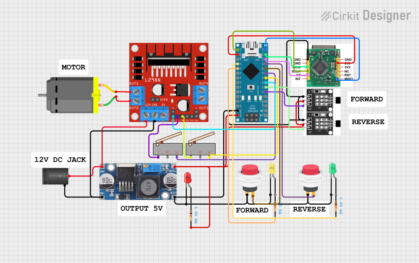
Example Circuit
- Use an L298N motor driver to control the motor.
- Connect the Hall sensor's
Signalpin to an Arduino UNO's digital pin (e.g., D2).
Arduino Code Example
The following code demonstrates how to read the Hall sensor's output and calculate the motor's speed in RPM.
// Define pin for Hall sensor signal
const int hallSensorPin = 2;

// Variables to store pulse count and time
volatile int pulseCount = 0;
unsigned long lastTime = 0;
float rpm = 0;

// Interrupt service routine for counting pulses
void countPulses() {
  pulseCount++;
}

void setup() {
  // Initialize serial communication
  Serial.begin(9600);

  // Set Hall sensor pin as input
  pinMode(hallSensorPin, INPUT);

  // Attach interrupt to the Hall sensor pin
  attachInterrupt(digitalPinToInterrupt(hallSensorPin), countPulses, RISING);

  // Initialize timing
  lastTime = millis();
}

void loop() {
  // Calculate RPM every second
  unsigned long currentTime = millis();
  if (currentTime - lastTime >= 1000) {
    // Calculate RPM: (pulses per second) * (60 seconds per minute) / (pulses per revolution)
    rpm = (pulseCount * 60.0) / 2.0; // 2 pulses per revolution
    pulseCount = 0; // Reset pulse count
    lastTime = currentTime; // Update time

    // Print RPM to serial monitor
    Serial.print("Motor RPM: ");
    Serial.println(rpm);
  }
}
Important Considerations
- Power Supply: Ensure the motor and Hall sensor are powered within their specified voltage ranges to avoid damage.
- Debouncing: If the Hall sensor signal is noisy, consider adding a capacitor or software debouncing.
- Motor Driver: Use a motor driver capable of handling the motor's stall current to prevent damage.
Troubleshooting and FAQs
Common Issues
Motor Not Spinning
- Cause: Insufficient power supply or incorrect wiring.
- Solution: Verify the power supply voltage and check the motor connections.
No Signal from Hall Sensor
- Cause: Incorrect wiring or insufficient power to the Hall sensor.
- Solution: Ensure the
VCCandGNDpins are properly connected and theSignalpin is connected to the microcontroller.
Inaccurate RPM Readings
- Cause: Noise in the Hall sensor signal or incorrect pulse count calculation.
- Solution: Add a capacitor across the Hall sensor's power pins or implement software filtering.
FAQs
Can the N20 motor run without the Hall sensor?
- Yes, the motor can operate without using the Hall sensor, but you will lose speed and position feedback.
What is the maximum RPM the Hall sensor can measure?
- The maximum measurable RPM depends on the microcontroller's interrupt handling speed and the motor's pulse frequency.
Can I use the Hall sensor with a 3.3V microcontroller?
- Yes, the Hall sensor operates at 3.3V to 5V, making it compatible with most microcontrollers.
By following this documentation, you can effectively integrate the N20 motor with Hall sensor into your projects for precise motor control and feedback.