
How to Use Linear Servo Motor: Examples, Pinouts, and Specs
 Design with Linear Servo Motor in Cirkit Designer
Introduction
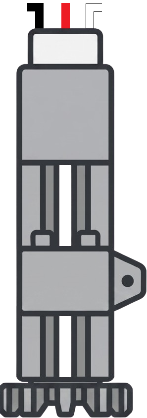
A linear servo motor is an electromechanical device that converts electrical energy into linear motion. Unlike traditional rotary motors, which require additional mechanisms to achieve linear movement, a linear servo motor directly produces linear displacement. It provides precise control of position, velocity, and acceleration, making it ideal for applications requiring accurate and repeatable movement.
Explore Projects Built with Linear Servo Motor
 Open Project in Cirkit Designer
 Open Project in Cirkit Designer
 Open Project in Cirkit Designer
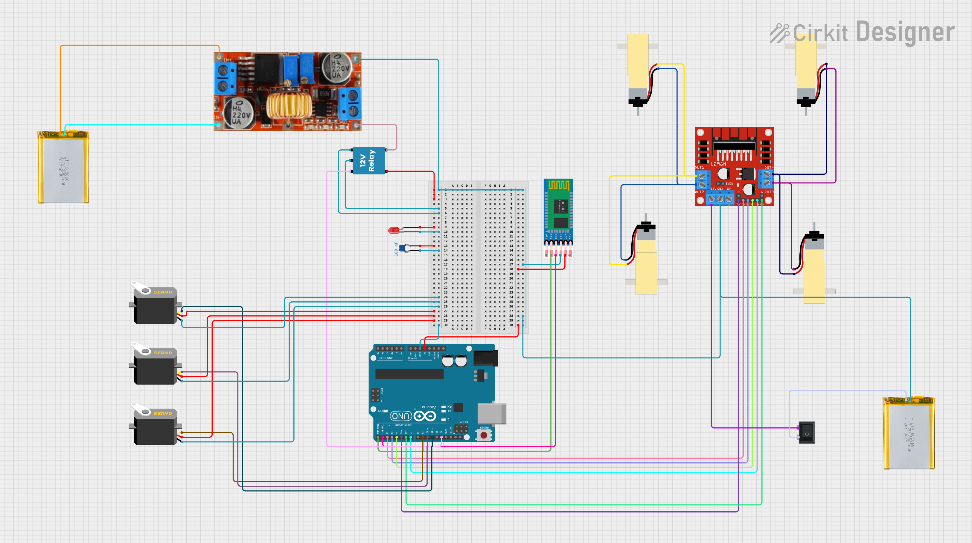 Open Project in Cirkit Designer
Explore Projects Built with Linear Servo Motor
Open Project in Cirkit DesignerOpen Project in Cirkit DesignerOpen Project in Cirkit DesignerOpen Project in Cirkit DesignerCommon Applications and Use Cases
- Robotics: For precise positioning and movement in robotic arms and grippers.
- Automation: Used in conveyor systems, pick-and-place machines, and CNC machinery.
- Medical Devices: For applications like surgical robots and diagnostic equipment.
- Aerospace: In flight simulators and control systems.
- Industrial Equipment: For material handling, packaging, and inspection systems.
Technical Specifications
Below are the general technical specifications for a typical linear servo motor. Note that specific models may vary, so always refer to the datasheet of your particular motor.
Key Technical Details
- Input Voltage: 12V to 48V DC (varies by model)
- Maximum Stroke Length: 50mm to 500mm
- Peak Force: 10N to 500N
- Position Accuracy: ±0.01mm
- Maximum Speed: 1m/s to 5m/s
- Control Signal: PWM (Pulse Width Modulation) or Analog (0-10V)
- Feedback Mechanism: Encoder or Hall Effect Sensor
- Operating Temperature: -20°C to 60°C
- Lifespan: >10 million cycles (depending on load and usage)
Pin Configuration and Descriptions
The pinout for a linear servo motor typically includes power, ground, control, and feedback connections. Below is a standard pin configuration:
| Pin | Name | Description |
|---|---|---|
| 1 | V+ (Power) | Positive power supply input (e.g., 12V or 24V DC). |
| 2 | GND (Ground) | Ground connection for the power supply. |
| 3 | PWM/Control | Control signal input for position or speed control (PWM or analog signal). |
| 4 | Feedback A | Encoder or Hall sensor feedback signal A for position tracking. |
| 5 | Feedback B | Encoder or Hall sensor feedback signal B (used for direction and speed sensing). |
Usage Instructions
How to Use the Component in a Circuit
- Power Supply: Connect the V+ and GND pins to a regulated DC power supply within the specified voltage range.
- Control Signal: Use a microcontroller (e.g., Arduino UNO) or a dedicated motor driver to send a PWM or analog signal to the control pin.
- Feedback Connection: Connect the feedback pins (A and B) to the microcontroller or motor driver for position and speed monitoring.
- Load Connection: Attach the load to the motor's linear actuator, ensuring it does not exceed the motor's rated force or stroke length.
Important Considerations and Best Practices
- Power Supply: Ensure the power supply can provide sufficient current for the motor's peak load.
- Signal Compatibility: Verify that the control signal (PWM frequency or analog voltage) matches the motor's specifications.
- Mounting: Securely mount the motor to prevent misalignment or vibration during operation.
- Feedback Calibration: If using an encoder, calibrate the feedback system to ensure accurate position tracking.
- Heat Dissipation: Avoid overheating by operating within the specified temperature range and providing adequate ventilation.
Example: Connecting a Linear Servo Motor to an Arduino UNO
Below is an example of how to control a linear servo motor using an Arduino UNO and a PWM signal.
// Example code to control a linear servo motor with Arduino UNO
// Ensure the motor's control pin is connected to Arduino pin 9

const int controlPin = 9; // PWM pin connected to the motor's control input
int position = 90;        // Initial position (0 to 180 degrees equivalent)

void setup() {
  pinMode(controlPin, OUTPUT); // Set the control pin as an output
}

void loop() {
  // Map position (0-180) to PWM signal (1000-2000 microseconds)
  int pwmSignal = map(position, 0, 180, 1000, 2000);

  // Send PWM signal to the motor
  analogWrite(controlPin, pwmSignal / 4); // Convert to 8-bit PWM (0-255)

  delay(1000); // Wait for 1 second before changing position

  // Change position for demonstration
  position = (position == 90) ? 180 : 90; // Toggle between 90 and 180 degrees
}
Troubleshooting and FAQs
Common Issues and Solutions
Motor Does Not Move:
- Cause: Insufficient power supply or incorrect wiring.
- Solution: Verify the power supply voltage and current. Check all connections.
Inaccurate Positioning:
- Cause: Feedback system not calibrated or noisy control signal.
- Solution: Calibrate the encoder or Hall sensor. Use a stable PWM signal.
Overheating:
- Cause: Operating beyond rated load or poor ventilation.
- Solution: Reduce the load or improve airflow around the motor.
Erratic Movement:
- Cause: Interference in the control signal or loose connections.
- Solution: Shield the control wires and ensure all connections are secure.
FAQs
Q: Can I use a linear servo motor with a battery?
- A: Yes, as long as the battery provides the required voltage and current. Ensure the battery is capable of handling peak loads.
Q: What is the difference between a linear servo motor and a stepper motor?
- A: A linear servo motor provides continuous feedback for precise control of position, velocity, and acceleration, while a stepper motor moves in discrete steps and lacks feedback unless paired with an encoder.
Q: How do I determine the correct motor for my application?
- A: Consider the required stroke length, force, speed, and accuracy. Ensure the motor's specifications meet or exceed your application's demands.
Q: Can I control multiple linear servo motors with one Arduino?
- A: Yes, but ensure the Arduino has enough PWM pins and processing power. Use external motor drivers if necessary.
This documentation provides a comprehensive guide to understanding and using a linear servo motor effectively. Always refer to the specific datasheet for your motor model for precise details.