Cirkit Designer Logo
Cirkit Designer
Your all-in-one circuit design IDE
Home / 
Component Documentation

How to Use BW16-Kit: Examples, Pinouts, and Specs

Image of BW16-Kit
Cirkit Designer LogoDesign with BW16-Kit in Cirkit Designer

Introduction

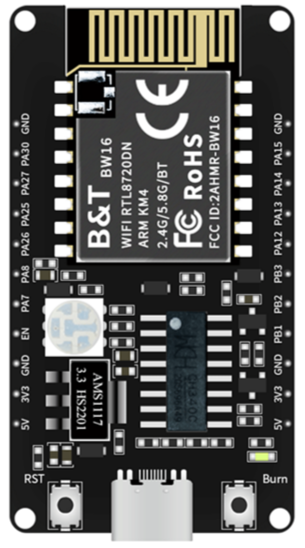
The BW16-Kit by AI Thinker is a development kit based on the RTL8720DN chip, which is a highly integrated Wi-Fi and Bluetooth module that supports dual bands for Wi-Fi communication and low-energy Bluetooth. This kit is designed for Internet of Things (IoT) applications and can be used in a variety of scenarios, including smart home devices, wireless audio, and industrial control.

Explore Projects Built with BW16-Kit

Use Cirkit Designer to design, explore, and prototype these projects online. Some projects support real-time simulation. Click "Open Project" to start designing instantly!
ESP32 and BW16-Kit-1 Microcontroller Communication Hub with Buzzer Notification
Image of BiJiQ Wi-Fi To.oL: A project utilizing BW16-Kit in a practical application
This circuit features two ESP32 microcontrollers configured to communicate with each other via serial connection, as indicated by the cross-connection of their TX2 and RX2 pins. A BW16-Kit-1 microcontroller is also included, interfacing with one of the ESP32s through pins D26 and D27. Power is supplied to the microcontrollers through a step-down buck converter connected to a 5V Type C DC socket, and a buzzer is driven by one of the ESP32s, potentially for audio signaling purposes.
Cirkit Designer LogoOpen Project in Cirkit Designer
ESP32-WROOM-32UE Wi-Fi Controlled Robotic Car with OLED Display and RGB LED
Image of mkrl bot: A project utilizing BW16-Kit in a practical application
This circuit is a WiFi-controlled robotic system powered by an ESP32 microcontroller. It features an OLED display for status messages, an RGB LED for visual feedback, and dual hobby gearmotors driven by an L9110 motor driver for movement. The system is powered by a 4 x AAA battery pack regulated to 5V using a 7805 voltage regulator.
Cirkit Designer LogoOpen Project in Cirkit Designer
ESP32-Based Environmental Monitoring and Alert System with Solar Charging
Image of Schematic: A project utilizing BW16-Kit in a practical application
This circuit features an ESP32 Devkit V1 microcontroller connected to various sensors and devices, including a DHT11 temperature and humidity sensor, an MQ-2 gas sensor, and a WS2812 RGB LED strip. The ESP32 controls the LED strip and processes sensor readings, while a SIM900A module provides cellular communication capabilities. Power management is handled by a UPS module fed by a 12V battery charged via a solar panel and charge controller, with voltage regulation provided by step-down converters. Additionally, a piezo buzzer is included for audible alerts, and the system's safety is ensured by a circuit breaker connected to a switching power supply for AC to DC conversion.
Cirkit Designer LogoOpen Project in Cirkit Designer
Dual-Microcontroller Audio Processing System with Visual Indicators and Battery Management
Image of proto thesis 2: A project utilizing BW16-Kit in a practical application
This is a portable audio-visual device featuring two Wemos microcontrollers for processing, Adafruit MAX4466 microphone amplifiers for audio input, and an LCD TFT screen for display. It includes power management with TP4056 modules and LiPo batteries, and user-controlled toggle and rocker switches.
Cirkit Designer LogoOpen Project in Cirkit Designer

Explore Projects Built with BW16-Kit

Use Cirkit Designer to design, explore, and prototype these projects online. Some projects support real-time simulation. Click "Open Project" to start designing instantly!
Image of BiJiQ Wi-Fi To.oL: A project utilizing BW16-Kit in a practical application
ESP32 and BW16-Kit-1 Microcontroller Communication Hub with Buzzer Notification
This circuit features two ESP32 microcontrollers configured to communicate with each other via serial connection, as indicated by the cross-connection of their TX2 and RX2 pins. A BW16-Kit-1 microcontroller is also included, interfacing with one of the ESP32s through pins D26 and D27. Power is supplied to the microcontrollers through a step-down buck converter connected to a 5V Type C DC socket, and a buzzer is driven by one of the ESP32s, potentially for audio signaling purposes.
Cirkit Designer LogoOpen Project in Cirkit Designer
Image of mkrl bot: A project utilizing BW16-Kit in a practical application
ESP32-WROOM-32UE Wi-Fi Controlled Robotic Car with OLED Display and RGB LED
This circuit is a WiFi-controlled robotic system powered by an ESP32 microcontroller. It features an OLED display for status messages, an RGB LED for visual feedback, and dual hobby gearmotors driven by an L9110 motor driver for movement. The system is powered by a 4 x AAA battery pack regulated to 5V using a 7805 voltage regulator.
Cirkit Designer LogoOpen Project in Cirkit Designer
Image of Schematic: A project utilizing BW16-Kit in a practical application
ESP32-Based Environmental Monitoring and Alert System with Solar Charging
This circuit features an ESP32 Devkit V1 microcontroller connected to various sensors and devices, including a DHT11 temperature and humidity sensor, an MQ-2 gas sensor, and a WS2812 RGB LED strip. The ESP32 controls the LED strip and processes sensor readings, while a SIM900A module provides cellular communication capabilities. Power management is handled by a UPS module fed by a 12V battery charged via a solar panel and charge controller, with voltage regulation provided by step-down converters. Additionally, a piezo buzzer is included for audible alerts, and the system's safety is ensured by a circuit breaker connected to a switching power supply for AC to DC conversion.
Cirkit Designer LogoOpen Project in Cirkit Designer
Image of proto thesis 2: A project utilizing BW16-Kit in a practical application
Dual-Microcontroller Audio Processing System with Visual Indicators and Battery Management
This is a portable audio-visual device featuring two Wemos microcontrollers for processing, Adafruit MAX4466 microphone amplifiers for audio input, and an LCD TFT screen for display. It includes power management with TP4056 modules and LiPo batteries, and user-controlled toggle and rocker switches.
Cirkit Designer LogoOpen Project in Cirkit Designer

Common Applications and Use Cases

  • Smart Home Automation
  • IoT Nodes and Gateways
  • Wireless Sensor Networks
  • Remote Control Systems
  • Wearable Electronics

Technical Specifications

Key Technical Details

  • Wi-Fi Standard: IEEE 802.11 a/b/g/n/ac (Dual-band Wi-Fi 2.4GHz and 5GHz)
  • Bluetooth Standard: Bluetooth 5.0
  • Operating Voltage: 3.3V
  • I/O Voltage Level: 3.3V
  • Flash Memory: 2MB
  • SRAM: 512KB
  • Operating Temperature: -40°C to 85°C

Pin Configuration and Descriptions

Pin Number Pin Name Description
1 3V3 Power supply (3.3V input)
2 GND Ground
3 TX UART Transmit
4 RX UART Receive
5 IO0 General-purpose I/O, boot mode selection
6 IO1 General-purpose I/O
... ... ...
n RST Reset pin, active low

Note: This is a simplified representation. Refer to the manufacturer's datasheet for the complete pinout and detailed descriptions.

Usage Instructions

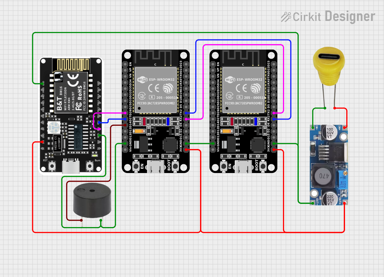
How to Use the Component in a Circuit

  1. Power Supply: Ensure that the BW16-Kit is powered with a stable 3.3V supply. Do not exceed the recommended voltage to prevent damage.

  2. Serial Communication: Connect the TX and RX pins to a serial interface for programming and debugging. Use a USB-to-UART adapter if necessary.

  3. GPIO: Utilize the general-purpose I/O pins for interfacing with sensors, actuators, or other peripherals as required by your application.

  4. Reset: The RST pin can be used to reset the module. Connect a push-button to this pin for manual reset functionality.

Important Considerations and Best Practices

  • Always ensure that the power supply is clean and within the specified voltage range.
  • When programming the module, ensure that the IO0 pin is set to the correct state to enter the programming mode.
  • Use proper ESD precautions when handling the BW16-Kit to avoid electrostatic damage.
  • Ensure that the antenna area is kept clear of metal objects to avoid interference with the wireless signals.

Troubleshooting and FAQs

Common Issues Users Might Face

  • Power Issues: If the module does not power on, check the power supply and connections.
  • Connectivity Problems: Ensure the antenna is properly connected and not obstructed.
  • Programming Errors: Verify that the correct drivers are installed and that the IO0 pin is set correctly for programming mode.

Solutions and Tips for Troubleshooting

  • Double-check wiring and solder joints for any loose connections or shorts.
  • Use a multimeter to verify the voltage levels at the power supply and I/O pins.
  • Consult the manufacturer's datasheet and user forums for specific troubleshooting advice.

FAQs

Q: Can the BW16-Kit be used with an Arduino UNO?

A: Yes, it can be interfaced with an Arduino UNO using serial communication (UART) or other available I/O pins.

Q: What is the maximum range of the Wi-Fi and Bluetooth signals?

A: The range depends on various factors, including the environment and antenna used. Typically, Wi-Fi can reach up to 100 meters in open space, and Bluetooth range is around 10 meters.

Q: How do I update the firmware on the BW16-Kit?

A: Firmware updates can be done through the UART interface using the provided tools and instructions from AI Thinker.

Q: Is the BW16-Kit compatible with the Arduino IDE?

A: Yes, with the proper board support package installed, the BW16-Kit can be programmed using the Arduino IDE.

Example Code for Arduino UNO

// Example code for interfacing BW16-Kit with Arduino UNO
#include <SoftwareSerial.h>

SoftwareSerial bw16Serial(10, 11); // RX, TX

void setup() {
  // Start the built-in serial port, for debugging
  Serial.begin(9600);
  // Start the software serial port, to communicate with the BW16-Kit
  bw16Serial.begin(115200);
}

void loop() {
  // Check if data has been received from the BW16-Kit
  if (bw16Serial.available()) {
    char c = bw16Serial.read();
    // Print any received data to the built-in serial port
    Serial.write(c);
  }

  // Check if data has been received from the built-in serial port
  if (Serial.available()) {
    char c = Serial.read();
    // Send any received data out through the BW16-Kit
    bw16Serial.write(c);
  }
}

Note: This example uses software serial for communication. For more robust applications, hardware serial is recommended.

Remember to consult the BW16-Kit datasheet and technical reference for more detailed information and advanced usage scenarios.