How to Use MFRC RFID522_d5542a2cc23721db3fcbe4ea437685a4_3_schematic: Examples, Pinouts, and Specs
Introduction
The MFRC RFID522 is a highly integrated reader/writer designed for contactless communication at a frequency of 13.56 MHz. It is widely used in RFID (Radio Frequency Identification) applications for reading and writing data to RFID tags. The module supports multiple protocols, including ISO/IEC 14443 A/MIFARE, and provides a simple SPI interface for communication with microcontrollers.
Explore Projects Built with MFRC RFID522_d5542a2cc23721db3fcbe4ea437685a4_3_schematic
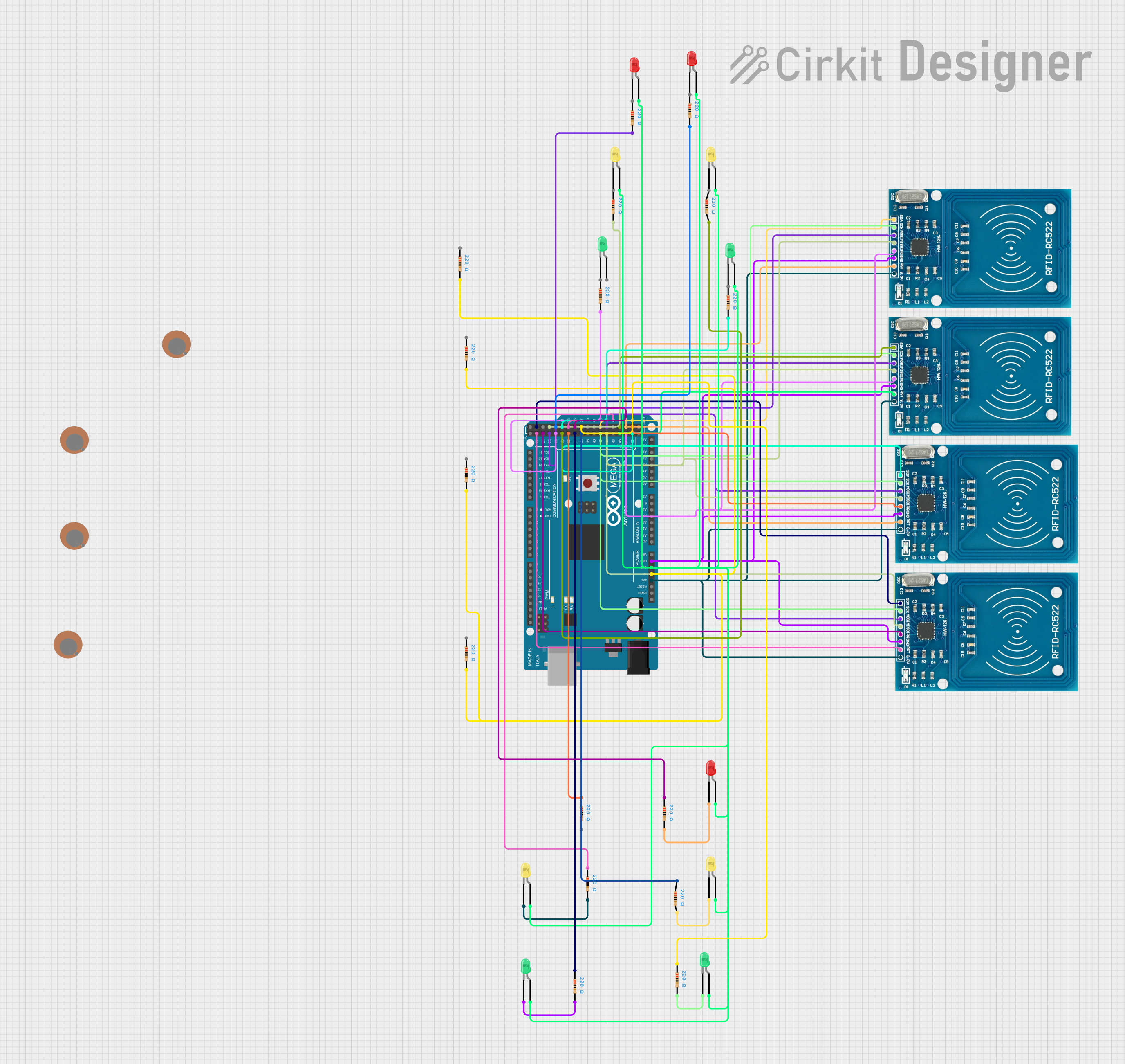
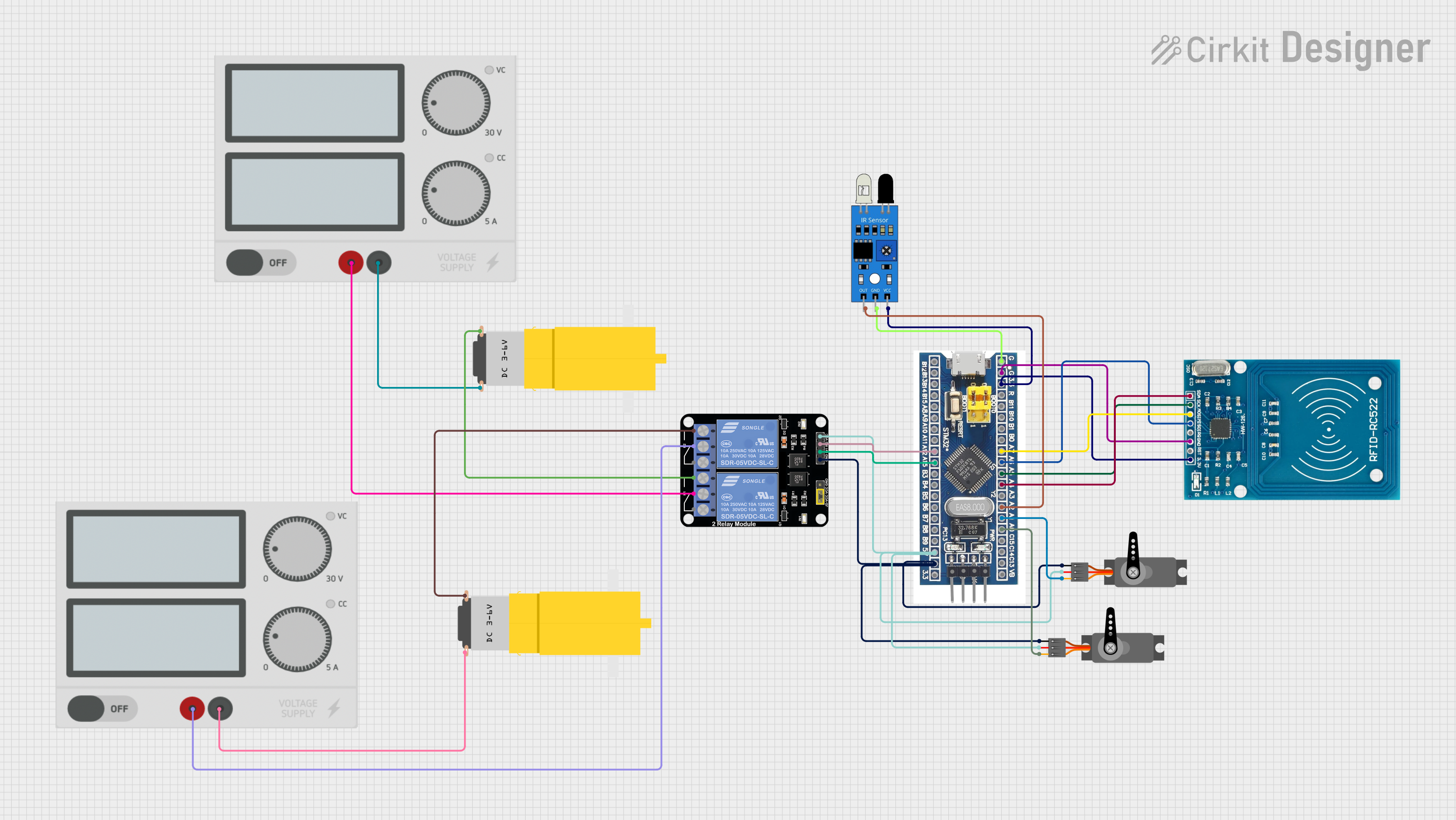
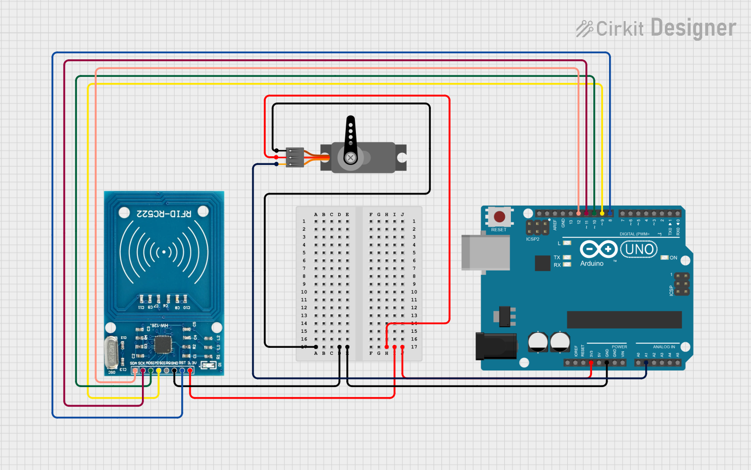
Explore Projects Built with MFRC RFID522_d5542a2cc23721db3fcbe4ea437685a4_3_schematic
Common Applications and Use Cases
- Access control systems (e.g., door locks, attendance systems)
- Contactless payment systems
- Inventory management and tracking
- Smart card applications
- Embedded systems requiring RFID functionality
Technical Specifications
Key Technical Details
- Operating Voltage: 2.5V to 3.3V (logic level), typically powered via 3.3V
- Operating Frequency: 13.56 MHz
- Communication Interface: SPI, I2C, or UART (SPI is most commonly used)
- Maximum Data Rate: 424 kbit/s
- Supported Protocols: ISO/IEC 14443 A/MIFARE
- Current Consumption: ~13-26 mA during operation, ~10 µA in standby mode
- Operating Temperature: -20°C to +85°C
- Antenna: Integrated or external antenna support
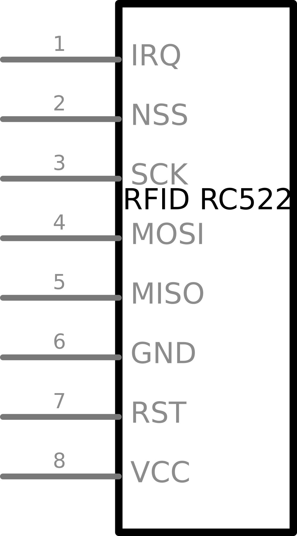
Pin Configuration and Descriptions
The MFRC522 module typically comes with an 8-pin header for interfacing. Below is the pinout:
| Pin | Name | Description |
|---|---|---|
| 1 | VCC | Power supply input (3.3V). |
| 2 | RST | Reset pin. Active LOW. Used to reset the module. |
| 3 | GND | Ground connection. |
| 4 | IRQ | Interrupt pin. Can be used to signal events to the microcontroller. |
| 5 | MISO/SCL | SPI Master-In-Slave-Out (data output) or I2C clock line (SCL). |
| 6 | MOSI/SDA | SPI Master-Out-Slave-In (data input) or I2C data line (SDA). |
| 7 | SCK | SPI clock input. |
| 8 | NSS/SDA(SS) | SPI chip select (active LOW) or I2C address selection. |
Note: The module is typically used in SPI mode, and the I2C/UART modes are less common.
Usage Instructions
How to Use the MFRC522 in a Circuit
- Power the Module: Connect the VCC pin to a 3.3V power source and GND to ground.
- Connect to a Microcontroller: Use the SPI interface to connect the module to a microcontroller (e.g., Arduino UNO). The typical connections are:
VCC→ 3.3VGND→ GNDRST→ Any digital pin (e.g., D9 on Arduino UNO)IRQ→ Not required for basic operationMISO→ Arduino UNO pin 12MOSI→ Arduino UNO pin 11SCK→ Arduino UNO pin 13NSS→ Arduino UNO pin 10
- Install Required Libraries: For Arduino, install the "MFRC522" library from the Arduino Library Manager.
- Write Code: Use the library functions to initialize the module, read RFID tags, and write data.
Example Arduino Code
Below is an example of how to use the MFRC522 module with an Arduino UNO to read RFID tags:
#include <SPI.h>
#include <MFRC522.h>

// Define MFRC522 pins
#define RST_PIN 9  // Reset pin connected to Arduino pin 9
#define SS_PIN 10  // Slave Select pin connected to Arduino pin 10

// Create an instance of the MFRC522 class
MFRC522 rfid(SS_PIN, RST_PIN);

void setup() {
  Serial.begin(9600); // Initialize serial communication
  SPI.begin();        // Initialize SPI bus
  rfid.PCD_Init();    // Initialize the MFRC522 module
  Serial.println("Place your RFID card near the reader...");
}

void loop() {
  // Check if an RFID card is present
  if (!rfid.PICC_IsNewCardPresent() || !rfid.PICC_ReadCardSerial()) {
    return; // No card detected, exit the loop
  }

  // Print the UID (Unique Identifier) of the card
  Serial.print("Card UID: ");
  for (byte i = 0; i < rfid.uid.size; i++) {
    Serial.print(rfid.uid.uidByte[i] < 0x10 ? " 0" : " ");
    Serial.print(rfid.uid.uidByte[i], HEX);
  }
  Serial.println();

  // Halt the card to stop communication
  rfid.PICC_HaltA();
}
Important Considerations and Best Practices
- Voltage Levels: The MFRC522 operates at 3.3V logic levels. If using a 5V microcontroller (e.g., Arduino UNO), use level shifters to avoid damaging the module.
- Antenna Placement: Ensure the antenna is not obstructed by metal objects, as this can interfere with communication.
- Tag Compatibility: The module supports ISO/IEC 14443 A/MIFARE tags. Ensure your tags are compatible.
- Library Updates: Always use the latest version of the MFRC522 library for optimal performance and bug fixes.
Troubleshooting and FAQs
Common Issues and Solutions
The module is not detected by the microcontroller.
- Check all connections, especially the SPI pins.
- Ensure the module is powered with 3.3V and not 5V.
- Verify that the
SS_PINandRST_PINin the code match your wiring.
The RFID tag is not being read.
- Ensure the tag is compatible with the MFRC522 (e.g., MIFARE tags).
- Place the tag closer to the antenna.
- Check for interference from nearby metal objects or other RFID devices.
The module heats up during operation.
- Verify that the module is powered with 3.3V and not 5V.
- Check for short circuits in the wiring.
The UID is not displayed correctly.
- Ensure the serial monitor baud rate matches the
Serial.begin()value in the code. - Verify that the RFID tag is functioning properly.
- Ensure the serial monitor baud rate matches the
FAQs
Q: Can the MFRC522 write data to RFID tags?
A: Yes, the MFRC522 can write data to compatible RFID tags, such as MIFARE Classic cards. Use the appropriate library functions for writing.
Q: Can I use the MFRC522 with a 5V microcontroller?
A: Yes, but you must use level shifters to convert the 5V logic levels to 3.3V to avoid damaging the module.
Q: What is the maximum range of the MFRC522?
A: The typical range is 2-5 cm, depending on the antenna design and tag type.
Q: Can I connect multiple MFRC522 modules to a single microcontroller?
A: Yes, you can connect multiple modules by using separate SS_PIN values for each module and managing them in your code.
This concludes the documentation for the MFRC RFID522 module.