Cirkit Designer Logo
Cirkit Designer
Your all-in-one circuit design IDE
Home / 
Component Documentation

How to Use Adafruit 1.54inch Tri-Color eInk-ePaper Display: Examples, Pinouts, and Specs

Image of Adafruit 1.54inch Tri-Color eInk-ePaper Display
Cirkit Designer LogoDesign with Adafruit 1.54inch Tri-Color eInk-ePaper Display in Cirkit Designer

Introduction

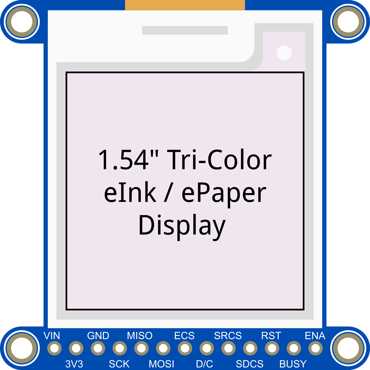
The Adafruit 1.54inch Tri-Color eInk/ePaper Display is a versatile and energy-efficient display module that is perfect for applications where power consumption and readability in various lighting conditions are crucial. This display utilizes e-ink technology, which mimics the appearance of ink on paper, providing excellent readability even in direct sunlight. The tri-color capability allows it to display images and text in red, black, and white, making it suitable for a wide range of applications such as digital signage, price tags, wearable devices, and any project where a low-power display is needed.

Explore Projects Built with Adafruit 1.54inch Tri-Color eInk-ePaper Display

Use Cirkit Designer to design, explore, and prototype these projects online. Some projects support real-time simulation. Click "Open Project" to start designing instantly!
Arduino Nano Controlled TFT Display with Multiple Pushbuttons
Image of rey: A project utilizing Adafruit 1.54inch Tri-Color eInk-ePaper Display in a practical application
This circuit features an Arduino Nano microcontroller connected to a ST7735 128x128 1.44 TFT I2C Color display and multiple pushbuttons. The display is interfaced with the Arduino via digital pins for control signals and SPI pins for data transfer. The pushbuttons are connected to various digital and analog input pins on the Arduino, likely intended for user input to control the display or other functions within the code.
Cirkit Designer LogoOpen Project in Cirkit Designer
Arduino-Based RGB Color Detection System with OLED and LCD Displays
Image of 1: A project utilizing Adafruit 1.54inch Tri-Color eInk-ePaper Display in a practical application
This circuit uses an Arduino UNO to interface with an Adafruit TCS34725 RGB color sensor, a 128x64 OLED display, and a 16x2 I2C LCD. The Arduino reads color data from the sensor and displays the color information on both the OLED and LCD screens.
Cirkit Designer LogoOpen Project in Cirkit Designer
Arduino Mega 2560 Controlled RFID and LCD Interface System
Image of Liquid Crystal Displays (LCD) with Arduino: A project utilizing Adafruit 1.54inch Tri-Color eInk-ePaper Display in a practical application
This circuit features an Arduino Mega 2560 microcontroller connected to an LCD display for visual output and an RFID-RC522 module for RFID reading capabilities. A trimmer potentiometer is used to adjust the contrast of the LCD, and a resistor is connected to provide backlighting for the display. The Arduino is programmed to interact with these components, likely to display information read from RFID tags and adjust display settings.
Cirkit Designer LogoOpen Project in Cirkit Designer
Arduino 101 OLED Display Animation Project
Image of wokwi animater test: A project utilizing Adafruit 1.54inch Tri-Color eInk-ePaper Display in a practical application
This circuit consists of an Arduino 101 microcontroller connected to a 0.96" OLED display via I2C communication. The Arduino runs a program that initializes the OLED and continuously displays an animated sequence of frames on the screen.
Cirkit Designer LogoOpen Project in Cirkit Designer

Explore Projects Built with Adafruit 1.54inch Tri-Color eInk-ePaper Display

Use Cirkit Designer to design, explore, and prototype these projects online. Some projects support real-time simulation. Click "Open Project" to start designing instantly!
Image of rey: A project utilizing Adafruit 1.54inch Tri-Color eInk-ePaper Display in a practical application
Arduino Nano Controlled TFT Display with Multiple Pushbuttons
This circuit features an Arduino Nano microcontroller connected to a ST7735 128x128 1.44 TFT I2C Color display and multiple pushbuttons. The display is interfaced with the Arduino via digital pins for control signals and SPI pins for data transfer. The pushbuttons are connected to various digital and analog input pins on the Arduino, likely intended for user input to control the display or other functions within the code.
Cirkit Designer LogoOpen Project in Cirkit Designer
Image of 1: A project utilizing Adafruit 1.54inch Tri-Color eInk-ePaper Display in a practical application
Arduino-Based RGB Color Detection System with OLED and LCD Displays
This circuit uses an Arduino UNO to interface with an Adafruit TCS34725 RGB color sensor, a 128x64 OLED display, and a 16x2 I2C LCD. The Arduino reads color data from the sensor and displays the color information on both the OLED and LCD screens.
Cirkit Designer LogoOpen Project in Cirkit Designer
Image of Liquid Crystal Displays (LCD) with Arduino: A project utilizing Adafruit 1.54inch Tri-Color eInk-ePaper Display in a practical application
Arduino Mega 2560 Controlled RFID and LCD Interface System
This circuit features an Arduino Mega 2560 microcontroller connected to an LCD display for visual output and an RFID-RC522 module for RFID reading capabilities. A trimmer potentiometer is used to adjust the contrast of the LCD, and a resistor is connected to provide backlighting for the display. The Arduino is programmed to interact with these components, likely to display information read from RFID tags and adjust display settings.
Cirkit Designer LogoOpen Project in Cirkit Designer
Image of wokwi animater test: A project utilizing Adafruit 1.54inch Tri-Color eInk-ePaper Display in a practical application
Arduino 101 OLED Display Animation Project
This circuit consists of an Arduino 101 microcontroller connected to a 0.96" OLED display via I2C communication. The Arduino runs a program that initializes the OLED and continuously displays an animated sequence of frames on the screen.
Cirkit Designer LogoOpen Project in Cirkit Designer

Technical Specifications

Key Technical Details

  • Display Size: 1.54 inches
  • Resolution: 152 x 152 pixels
  • Color: Red, Black, White
  • Interface: SPI
  • Operating Voltage: 3.3V
  • Maximum Current: 50mA (typical refresh)
  • Refresh Time: 15 seconds (full refresh)

Pin Configuration and Descriptions

Pin Number Name Description
1 GND Ground
2 3V3 3.3V Power Supply
3 SCK SPI Clock
4 SDO SPI Data Out (MISO)
5 SDI SPI Data In (MOSI)
6 CS SPI Chip Select
7 D/C Data/Command Control
8 RST Reset
9 BUSY Busy Status Indicator

Usage Instructions

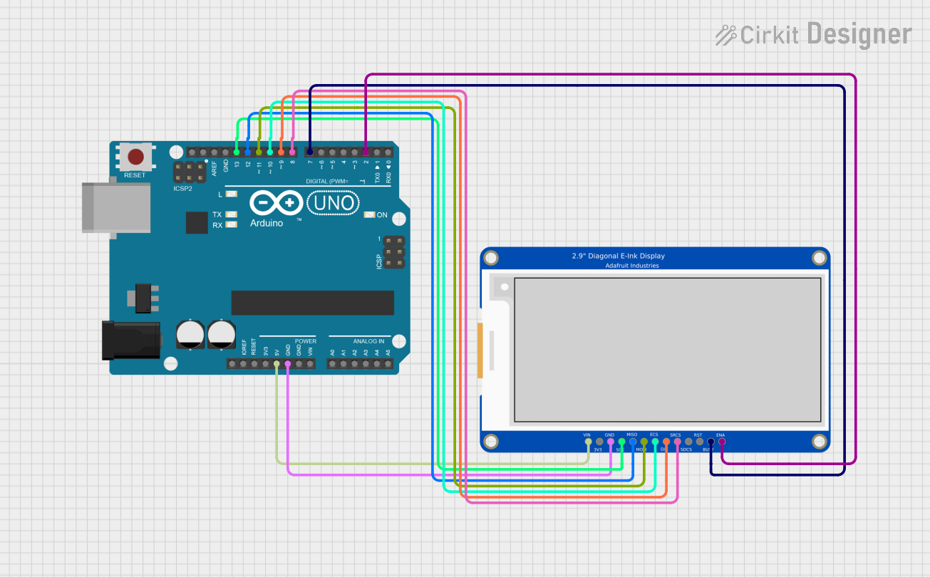
Integration with a Circuit

To use the Adafruit 1.54inch Tri-Color eInk/ePaper Display in a circuit:

  1. Connect the display's power pins (GND and 3V3) to your power source.
  2. Interface the SPI pins (SCK, SDO, SDI, and CS) with your microcontroller or development board.
  3. Connect the D/C pin to a digital pin on your microcontroller to switch between data and command mode.
  4. Connect the RST pin to another digital pin for resetting the display.
  5. The BUSY pin can be connected to a digital pin to read the display's status.

Best Practices

  • Ensure that the power supply is stable and does not exceed 3.3V.
  • Use a level shifter if you are interfacing with a 5V microcontroller.
  • Avoid bending the display as it is fragile.
  • Keep the display away from moisture and extreme temperatures.

Example Code for Arduino UNO

#include <Adafruit_EPD.h>
#include <Adafruit_GFX.h>

// Pin definitions
#define EPD_CS     10
#define EPD_DC     9
#define EPD_RST    8
#define EPD_BUSY   7
#define SRAM_CS    6
#define EPD_MOSI   11
#define EPD_SCK    13

// Create display instance
Adafruit_IL0373 display(152, 152, EPD_DC, EPD_RST, EPD_CS, SRAM_CS, EPD_MOSI, EPD_SCK, EPD_BUSY);

void setup() {
  display.begin(); // Initialize the display
  display.clearBuffer(); // Clear the buffer
  display.setTextColor(EPD_BLACK); // Set text color
  display.setCursor(0, 0); // Set cursor position
  display.print("Hello, ePaper!"); // Print text
  display.display(); // Update the display
}

void loop() {
  // Nothing to do here
}

Ensure that you have installed the Adafruit EPD library before uploading this code to your Arduino UNO. The code initializes the display, clears the buffer, sets the text color, and prints "Hello, ePaper!" on the screen.

Troubleshooting and FAQs

Common Issues

  • Display not updating: Ensure that all connections are secure and the correct pins are used. Also, check that the power supply is 3.3V.
  • Garbled or incomplete image: This could be due to a partial refresh. Try performing a full refresh of the display.
  • Display is unresponsive: Verify that the display is correctly reset and that the BUSY pin is being monitored before sending new commands.

Solutions and Tips

  • Always perform a full reset of the display during the setup.
  • Monitor the BUSY pin before sending new commands to ensure the display is ready.
  • If using a 5V microcontroller, use a level shifter to prevent damage to the display.

FAQs

Q: Can the display show images? A: Yes, the display can show images in red, black, and white. You will need to convert your images to a compatible format using image processing software.

Q: How often can the display be updated? A: The display can be updated as often as needed, but frequent updates will increase power consumption and may reduce the lifespan of the display.

Q: Is the display readable in the dark? A: No, e-ink displays do not emit light and require external light to be readable, similar to paper.