How to Use REV power distribution hub: Examples, Pinouts, and Specs
Introduction
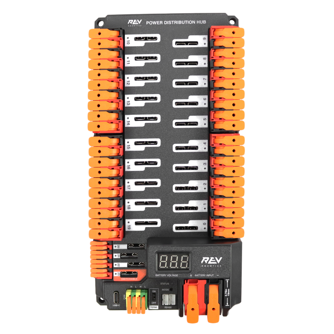
The REV Power Distribution Hub, manufactured by REV Robotics, is a centralized unit designed to distribute electrical power efficiently to various components in a robotic or electronic system. It ensures reliable power management, simplifies wiring, and provides robust connectivity for complex systems. This hub is particularly suited for robotics applications, where multiple devices such as motors, sensors, and controllers require stable and organized power distribution.
Explore Projects Built with REV power distribution hub


Explore Projects Built with REV power distribution hub
Common Applications and Use Cases
- Robotics systems in educational, competitive, and industrial environments
- Power management for motor controllers, sensors, and other electronic devices
- Projects requiring centralized and organized power distribution
- Systems with multiple voltage requirements or high-current demands
Technical Specifications
The REV Power Distribution Hub is engineered to handle high-current loads and provide multiple output channels for versatile power distribution. Below are the key technical details:
General Specifications
| Parameter | Value |
|---|---|
| Input Voltage Range | 6V to 15V |
| Maximum Continuous Current | 120A |
| Number of Output Channels | 20 |
| Output Voltage Options | Configurable (e.g., 5V, 12V) |
| Communication Interface | CAN Bus, USB |
| Dimensions | 120mm x 80mm x 30mm |
| Weight | 200g |
Pin Configuration and Descriptions
The REV Power Distribution Hub features multiple input and output terminals for flexible connectivity. Below is a detailed description of the pin configuration:
Input Terminals
| Pin Name | Description |
|---|---|
| VIN+ | Positive input terminal for power supply |
| VIN- | Negative input terminal (ground) |
Output Terminals
| Pin Name | Description |
|---|---|
| CH1 to CH20 | Configurable output channels for devices |
Communication Ports
| Port Name | Description |
|---|---|
| CAN Bus | For communication with controllers or devices |
| USB | For firmware updates and diagnostics |
Usage Instructions
The REV Power Distribution Hub is straightforward to integrate into your system. Follow these steps and best practices to ensure optimal performance:
Step-by-Step Instructions
Power Supply Connection:
- Connect the positive terminal of your power supply to the
VIN+input. - Connect the negative terminal of your power supply to the
VIN-input. - Ensure the power supply voltage is within the 6V to 15V range.
- Connect the positive terminal of your power supply to the
Device Connections:
- Connect your devices (e.g., motor controllers, sensors) to the output channels (
CH1toCH20). - Configure the output voltage for each channel as needed (refer to the hub's user manual for configuration details).
- Connect your devices (e.g., motor controllers, sensors) to the output channels (
Communication Setup:
- If using a CAN Bus, connect the hub to your controller via the CAN interface.
- For diagnostics or firmware updates, connect the hub to a computer using the USB port.
Power On:
- Once all connections are secure, power on the system and verify that all devices receive the correct voltage.
Important Considerations and Best Practices
- Current Limits: Ensure that the total current draw does not exceed the hub's maximum continuous current rating of 120A.
- Wire Gauge: Use appropriately rated wires for both input and output connections to handle the expected current.
- Fusing: Consider adding fuses or circuit breakers to protect your devices and the hub from overcurrent conditions.
- Ventilation: Install the hub in a well-ventilated area to prevent overheating during operation.
- Firmware Updates: Regularly check for firmware updates from REV Robotics to ensure compatibility and access to new features.
Example: Connecting to an Arduino UNO
The REV Power Distribution Hub can be used to power an Arduino UNO and other peripherals. Below is an example of how to connect the hub to an Arduino UNO:
- Connect the hub's
CH1output to the Arduino's VIN pin. - Set the output voltage of
CH1to 12V (if the Arduino is powered via VIN). - Use the CAN Bus or USB port for communication if needed.
Sample Arduino Code
// Example code to read data from a sensor powered by the REV Power Distribution Hub
// Ensure the sensor is connected to one of the hub's output channels.

const int sensorPin = A0; // Analog pin connected to the sensor
int sensorValue = 0;      // Variable to store the sensor reading

void setup() {
  Serial.begin(9600); // Initialize serial communication
  pinMode(sensorPin, INPUT); // Set the sensor pin as input
}

void loop() {
  sensorValue = analogRead(sensorPin); // Read the sensor value
  Serial.print("Sensor Value: ");
  Serial.println(sensorValue); // Print the sensor value to the Serial Monitor
  delay(500); // Wait for 500ms before the next reading
}
Troubleshooting and FAQs
Common Issues and Solutions
No Power to Devices:
- Cause: Incorrect input voltage or loose connections.
- Solution: Verify the input voltage is within the specified range and check all connections.
Overheating:
- Cause: Excessive current draw or poor ventilation.
- Solution: Reduce the load on the hub and ensure proper airflow around the unit.
Communication Failure:
- Cause: Faulty CAN Bus or USB connection.
- Solution: Check the communication cables and ensure the hub's firmware is up to date.
Output Voltage Incorrect:
- Cause: Misconfigured output channel settings.
- Solution: Reconfigure the output voltage for the affected channel.
FAQs
Q: Can the hub handle 24V input?
- A: No, the hub supports an input voltage range of 6V to 15V only.
Q: How do I update the firmware?
- A: Connect the hub to a computer via USB and use the REV Robotics firmware update tool.
Q: Can I use the hub in outdoor environments?
- A: The hub is not weatherproof. Use it in a dry, indoor environment or protect it with an enclosure.
By following this documentation, you can effectively integrate the REV Power Distribution Hub into your projects and ensure reliable power distribution for your electronic systems.