How to Use DIP Switch (2 Position): Examples, Pinouts, and Specs
Introduction
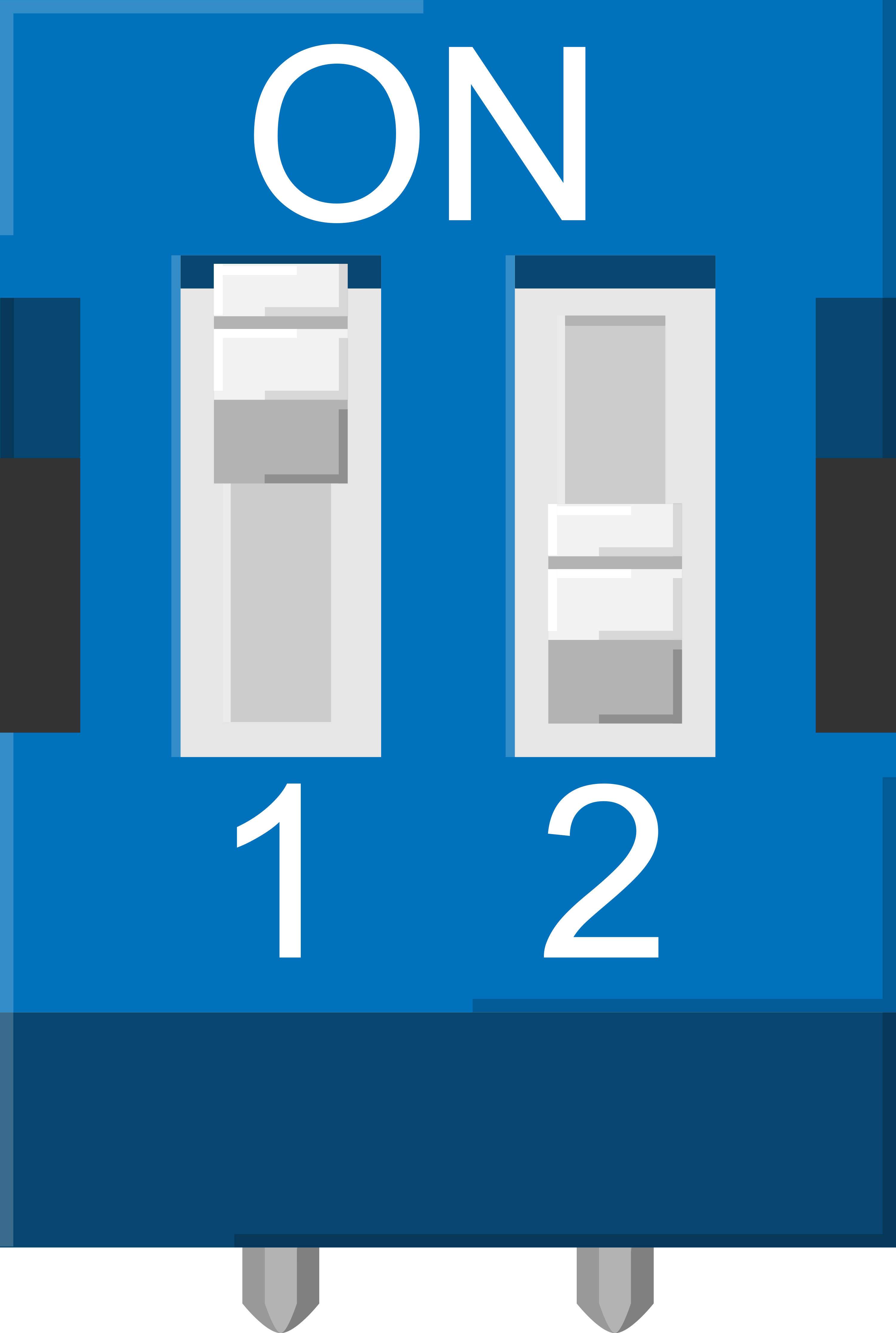
A DIP (Dual Inline Package) switch is a manual electrical switch packaged in a standard dual in-line configuration. The 2-position DIP switch allows for a simple on-off configuration in digital circuits, providing a convenient way to set or change options. These switches are often used for setting device addresses, configuration settings for computer peripherals, or as general-purpose input selectors in various electronic projects.
Explore Projects Built with DIP Switch (2 Position)
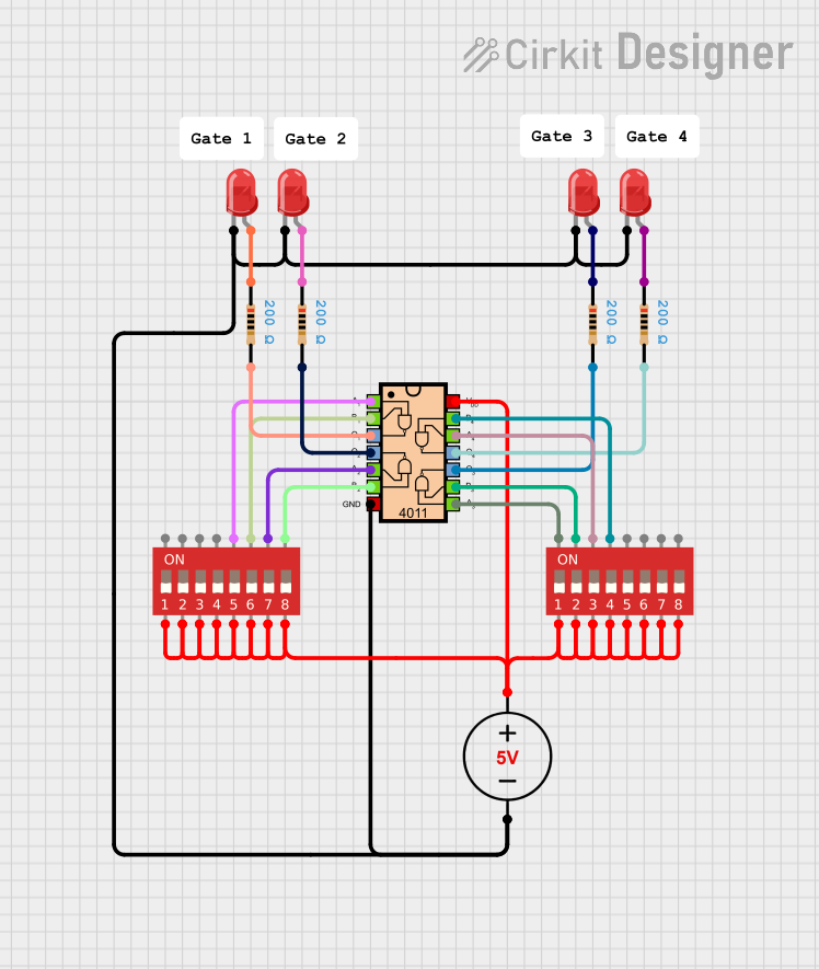

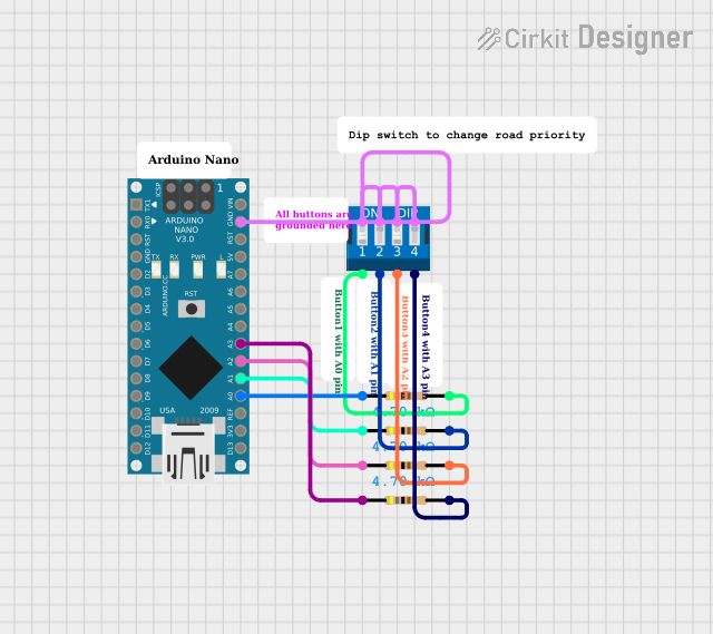

Explore Projects Built with DIP Switch (2 Position)
Common Applications and Use Cases
- Device address setting for networked devices
- Configuration settings for computer peripherals
- Input selectors for electronic circuits
- Function mode selectors in consumer electronics
- Prototype and development boards for testing purposes
Technical Specifications
Key Technical Details
- Voltage Rating: Typically 5V to 24V
- Current Rating: Often rated at 25mA to 100mA
- Contact Resistance: Usually less than 50 milliohms
- Insulation Resistance: Typically greater than 1000 megohms
- Dielectric Strength: Commonly 500VAC for 1 minute
- Operating Temperature Range: -40°C to +85°C
Pin Configuration and Descriptions
| Pin Number | Description |
|---|---|
| 1 | Common terminal 1 |
| 2 | Switch 1 output |
| 3 | Common terminal 2 |
| 4 | Switch 2 output |
Usage Instructions
How to Use the Component in a Circuit
- Powering the Switch: Connect the common terminals (pins 1 and 3) to the power supply (e.g., VCC) or ground, depending on the logic level desired when the switch is in the ON position.
- Output Connection: Connect the output pins (2 and 4) to the input pins of the device you wish to control or configure with the DIP switch.
- Setting the Switch: Use a small tool like a screwdriver to set the switch positions to ON or OFF as required for your application.
Important Considerations and Best Practices
- Debouncing: Although DIP switches do not typically bounce like push buttons, it is good practice to consider debouncing in software if the switch state is read frequently.
- Mounting: Ensure the DIP switch is properly seated on the PCB with all pins soldered to prevent intermittent connections.
- Switch Handling: Use appropriate force when changing switch positions to avoid damaging the switch mechanism.
Troubleshooting and FAQs
Common Issues Users Might Face
- Intermittent Connections: This can be due to poor soldering or debris in the switch. Check solder joints and clean the switch if necessary.
- Incorrect Logic Levels: Ensure that the common terminals are connected to the correct power supply level for your logic circuit.
Solutions and Tips for Troubleshooting
- Check Continuity: Use a multimeter to check for continuity between the common terminal and the output when the switch is in the ON position.
- Visual Inspection: Look for any signs of damage or improper soldering on the DIP switch and surrounding PCB area.
FAQs
Q: Can I use a DIP switch with higher voltage ratings in a 5V circuit? A: Yes, DIP switches with higher voltage ratings can be used safely in lower voltage applications.
Q: How do I know if the DIP switch is in the ON position? A: The ON position is typically when the switch actuator is pushed towards the numbered side of the switch body.
Q: Is it possible to change the position of a DIP switch while the power is on? A: Yes, but it is generally recommended to power down the system before changing switch positions to avoid potential issues.
Example Code for Arduino UNO
// Define the DIP switch pins
const int dipSwitch1 = 2; // Connect to pin 2 of the Arduino
const int dipSwitch2 = 3; // Connect to pin 3 of the Arduino

void setup() {
  // Set the DIP switch pins as input
  pinMode(dipSwitch1, INPUT_PULLUP);
  pinMode(dipSwitch2, INPUT_PULLUP);
  Serial.begin(9600);
}

void loop() {
  // Read the state of the DIP switches
  bool switchState1 = digitalRead(dipSwitch1);
  bool switchState2 = digitalRead(dipSwitch2);

  // Print the state of the switches to the Serial Monitor
  Serial.print("Switch 1 is ");
  Serial.print(switchState1 ? "ON" : "OFF");
  Serial.print(", Switch 2 is ");
  Serial.println(switchState2 ? "ON" : "OFF");

  // Add a delay to reduce the frequency of Serial prints
  delay(500);
}
Note: The INPUT_PULLUP mode is used to enable the internal pull-up resistors. When the switch is in the OFF position, the pin is pulled high. When the switch is ON, the pin is connected to ground and reads low.