
How to Use Screw terminal - 2 pins: Examples, Pinouts, and Specs

 Design with Screw terminal - 2 pins in Cirkit Designer
Introduction
The screw terminal (2 pins) is a type of electrical connector designed for securely attaching wires using screws. It features two pins, making it ideal for connecting two wires in a reliable and reusable manner. This component is widely used in electrical and electronic applications due to its simplicity, durability, and ease of use.
Explore Projects Built with Screw terminal - 2 pins
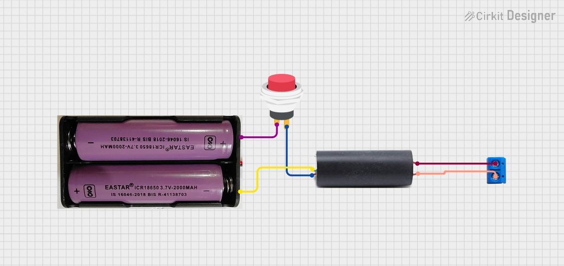 Open Project in Cirkit Designer
 Open Project in Cirkit Designer
 Open Project in Cirkit Designer
 Open Project in Cirkit Designer
Explore Projects Built with Screw terminal - 2 pins
Open Project in Cirkit DesignerOpen Project in Cirkit DesignerOpen Project in Cirkit DesignerOpen Project in Cirkit DesignerCommon Applications and Use Cases
- Connecting wires in prototyping and breadboard setups
- Power supply connections in low-voltage circuits
- Industrial control systems and automation
- Audio and speaker connections
- Home electrical wiring for small devices
Technical Specifications
Key Technical Details
| Parameter | Value |
|---|---|
| Number of Pins | 2 |
| Rated Voltage | Typically up to 300V (varies by model) |
| Rated Current | Typically up to 10A (varies by model) |
| Wire Gauge Compatibility | 12-24 AWG (varies by model) |
| Material | Plastic housing, metal screws, and terminals |
| Mounting Style | PCB mount or free-standing |
| Operating Temperature | -40°C to +105°C (varies by model) |
Pin Configuration and Descriptions
| Pin Number | Description |
|---|---|
| 1 | Terminal for wire connection (positive or signal) |
| 2 | Terminal for wire connection (negative or ground) |
Usage Instructions
How to Use the Component in a Circuit
- Prepare the Wires: Strip the insulation from the ends of the wires you want to connect. Ensure the exposed wire length matches the terminal's specifications (typically 5-7 mm).
- Insert the Wires: Loosen the screws on the terminal using a screwdriver. Insert the stripped wire ends into the terminal openings.
- Secure the Wires: Tighten the screws to clamp the wires securely in place. Avoid overtightening, as this may damage the wires or the terminal.
- Connect to Circuit: Solder or mount the screw terminal onto a PCB, or use it as a free-standing connector in your circuit.
Important Considerations and Best Practices
- Wire Compatibility: Ensure the wire gauge matches the terminal's specifications for a secure connection.
- Avoid Overloading: Do not exceed the rated voltage or current of the terminal.
- Tighten Properly: Ensure screws are tightened adequately to prevent loose connections, which can lead to overheating or signal loss.
- Insulation: Use heat shrink tubing or electrical tape to insulate exposed wires if necessary.
- Polarity: When connecting power supplies, ensure correct polarity to avoid damage to the circuit.
Example: Connecting to an Arduino UNO
The screw terminal can be used to connect external components, such as sensors or power supplies, to an Arduino UNO. Below is an example of connecting a 5V power supply to an Arduino using a screw terminal.
Circuit Setup
- Connect the positive wire from the 5V power supply to Pin 1 of the screw terminal.
- Connect the ground wire from the power supply to Pin 2 of the screw terminal.
- Use jumper wires to connect the screw terminal pins to the Arduino's 5V and GND pins.
Sample Code
// Example code for reading a sensor connected via a screw terminal
// This assumes the sensor's signal wire is connected to Arduino pin A0

const int sensorPin = A0; // Analog pin connected to the sensor
int sensorValue = 0;      // Variable to store the sensor reading

void setup() {
  Serial.begin(9600); // Initialize serial communication at 9600 baud
}

void loop() {
  sensorValue = analogRead(sensorPin); // Read the sensor value
  Serial.print("Sensor Value: ");
  Serial.println(sensorValue); // Print the sensor value to the Serial Monitor
  delay(1000); // Wait for 1 second before the next reading
}
Troubleshooting and FAQs
Common Issues and Solutions
| Issue | Possible Cause | Solution |
|---|---|---|
| Loose wire connections | Screws not tightened properly | Tighten screws securely but not excessively. |
| Overheating of terminal | Exceeding current rating | Ensure the current does not exceed the terminal's rating. |
| Wire slipping out of terminal | Incorrect wire gauge or improper insertion | Use wires within the specified gauge range and insert them fully. |
| Signal loss or noise | Poor contact or loose connections | Check and re-tighten connections; ensure wires are clean and undamaged. |
FAQs
Q: Can I use the screw terminal for high-voltage applications?
A: Screw terminals are typically rated for low to medium voltage (e.g., up to 300V). Always check the specific rating of your terminal before using it in high-voltage applications.
Q: How do I prevent wires from fraying when using the terminal?
A: You can use ferrules or tin the wire ends with solder to prevent fraying and ensure a secure connection.
Q: Can I reuse the screw terminal multiple times?
A: Yes, screw terminals are designed for repeated use. However, ensure the screws and threads remain in good condition for reliable connections.
Q: Is it safe to use the screw terminal outdoors?
A: Standard screw terminals are not weatherproof. For outdoor use, consider using weatherproof enclosures or terminals specifically designed for outdoor applications.