Cirkit Designer Logo
Cirkit Designer
Your all-in-one circuit design IDE
Home / 
Component Documentation

How to Use JC3248W535C Esp32: Examples, Pinouts, and Specs

Image of JC3248W535C Esp32
Cirkit Designer LogoDesign with JC3248W535C Esp32 in Cirkit Designer

Introduction

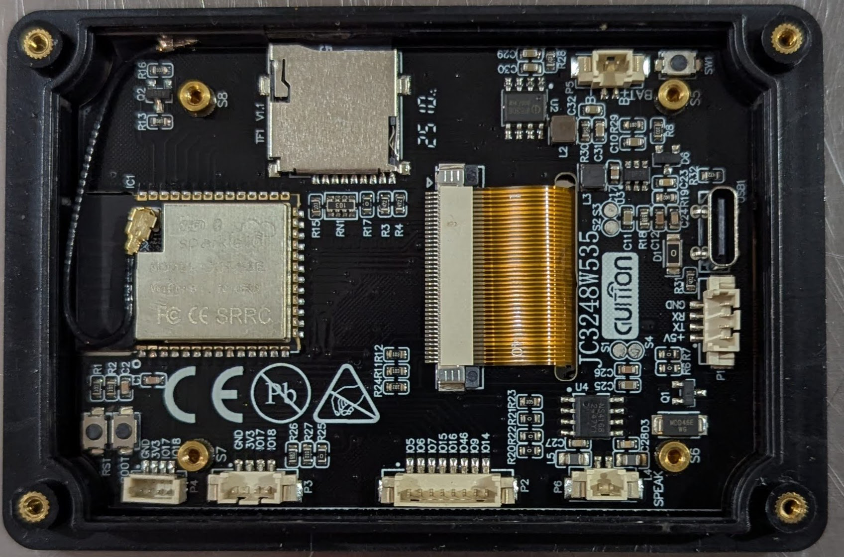
The JC3248W535C Esp32, manufactured by GUItion, is a high-performance, low-power microcontroller module designed for IoT (Internet of Things) applications. It is based on the ESP32 chipset, which integrates Wi-Fi and Bluetooth capabilities, making it ideal for wireless communication and smart device projects. This module is widely used in applications such as home automation, wearable devices, industrial IoT systems, and robotics.

The JC3248W535C Esp32 is particularly valued for its dual-core processor, extensive GPIO options, and support for multiple communication protocols, enabling developers to create versatile and efficient solutions.

Explore Projects Built with JC3248W535C Esp32

Use Cirkit Designer to design, explore, and prototype these projects online. Some projects support real-time simulation. Click "Open Project" to start designing instantly!
ESP32-Based Multi-Sensor Health Monitoring System with Bluetooth Connectivity
Image of circuit diagram: A project utilizing JC3248W535C Esp32 in a practical application
This circuit features an ESP32-WROOM-32UE microcontroller as the central processing unit, interfacing with a variety of sensors and modules. It includes a MAX30100 pulse oximeter and heart-rate sensor, an MLX90614 infrared thermometer, an HC-05 Bluetooth module for wireless communication, and a Neo 6M GPS module for location tracking. All components are powered by a common voltage supply and are connected to specific GPIO pins on the ESP32 for data exchange, with the sensors using I2C communication and the modules using UART.
Cirkit Designer LogoOpen Project in Cirkit Designer
ESP32-Based RF Communication System with 433 MHz Modules
Image of 433 mhz: A project utilizing JC3248W535C Esp32 in a practical application
This circuit comprises an ESP32 microcontroller connected to a 433 MHz RF transmitter and receiver pair. The ESP32 is programmed to receive and decode RF signals through the receiver module, as well as send RF signals via the transmitter module. Additionally, the ESP32 can communicate with a Bluetooth device to exchange commands and data, and it uses an LED for status indication.
Cirkit Designer LogoOpen Project in Cirkit Designer
ESP32-Powered Obstacle Avoidance Robot with IR and Ultrasonic Sensors
Image of projcememek: A project utilizing JC3248W535C Esp32 in a practical application
This circuit features a 18650 Li-Ion battery connected to a TP4056 charging module, which in turn is connected to an MT3608 boost converter to step up the voltage. The output of the MT3608 powers an ESP32 microcontroller, a TCRT 5000 IR sensor, an HC-SR04 ultrasonic sensor, and an MG996R servo motor. The ESP32 is configured to control the servo motor via GPIO 27 and to receive input signals from the IR sensor and ultrasonic sensor through GPIO 14 and GPIO 13, respectively.
Cirkit Designer LogoOpen Project in Cirkit Designer
ESP32-Based GPS Tracker with Bluetooth Connectivity and Camera Interface
Image of ESp32_gps: A project utilizing JC3248W535C Esp32 in a practical application
This circuit features an ESP32 microcontroller interfaced with a Neo 6M GPS Module, an OV7725 camera module, an HC-05 Bluetooth Module, and a BT139 600 triac. The ESP32 is programmed to read GPS data from the Neo 6M module and likely transmit it via Bluetooth using the HC-05 module. The OV7725 camera module is connected to the ESP32 for image capture, and the BT139 600 triac is interfaced for controlling power to an unspecified load.
Cirkit Designer LogoOpen Project in Cirkit Designer

Explore Projects Built with JC3248W535C Esp32

Use Cirkit Designer to design, explore, and prototype these projects online. Some projects support real-time simulation. Click "Open Project" to start designing instantly!
Image of circuit diagram: A project utilizing JC3248W535C Esp32 in a practical application
ESP32-Based Multi-Sensor Health Monitoring System with Bluetooth Connectivity
This circuit features an ESP32-WROOM-32UE microcontroller as the central processing unit, interfacing with a variety of sensors and modules. It includes a MAX30100 pulse oximeter and heart-rate sensor, an MLX90614 infrared thermometer, an HC-05 Bluetooth module for wireless communication, and a Neo 6M GPS module for location tracking. All components are powered by a common voltage supply and are connected to specific GPIO pins on the ESP32 for data exchange, with the sensors using I2C communication and the modules using UART.
Cirkit Designer LogoOpen Project in Cirkit Designer
Image of 433 mhz: A project utilizing JC3248W535C Esp32 in a practical application
ESP32-Based RF Communication System with 433 MHz Modules
This circuit comprises an ESP32 microcontroller connected to a 433 MHz RF transmitter and receiver pair. The ESP32 is programmed to receive and decode RF signals through the receiver module, as well as send RF signals via the transmitter module. Additionally, the ESP32 can communicate with a Bluetooth device to exchange commands and data, and it uses an LED for status indication.
Cirkit Designer LogoOpen Project in Cirkit Designer
Image of projcememek: A project utilizing JC3248W535C Esp32 in a practical application
ESP32-Powered Obstacle Avoidance Robot with IR and Ultrasonic Sensors
This circuit features a 18650 Li-Ion battery connected to a TP4056 charging module, which in turn is connected to an MT3608 boost converter to step up the voltage. The output of the MT3608 powers an ESP32 microcontroller, a TCRT 5000 IR sensor, an HC-SR04 ultrasonic sensor, and an MG996R servo motor. The ESP32 is configured to control the servo motor via GPIO 27 and to receive input signals from the IR sensor and ultrasonic sensor through GPIO 14 and GPIO 13, respectively.
Cirkit Designer LogoOpen Project in Cirkit Designer
Image of ESp32_gps: A project utilizing JC3248W535C Esp32 in a practical application
ESP32-Based GPS Tracker with Bluetooth Connectivity and Camera Interface
This circuit features an ESP32 microcontroller interfaced with a Neo 6M GPS Module, an OV7725 camera module, an HC-05 Bluetooth Module, and a BT139 600 triac. The ESP32 is programmed to read GPS data from the Neo 6M module and likely transmit it via Bluetooth using the HC-05 module. The OV7725 camera module is connected to the ESP32 for image capture, and the BT139 600 triac is interfaced for controlling power to an unspecified load.
Cirkit Designer LogoOpen Project in Cirkit Designer

Technical Specifications

The JC3248W535C Esp32 offers robust performance and flexibility. Below are its key technical details:

General Specifications

Parameter Value
Manufacturer GUItion
Part ID JC3248W535
Microcontroller ESP32 Dual-Core Processor
Clock Speed Up to 240 MHz
Flash Memory 4 MB
SRAM 520 KB
Wireless Connectivity Wi-Fi 802.11 b/g/n, Bluetooth 4.2 (BLE)
Operating Voltage 3.3V
Power Consumption Ultra-low power in deep sleep mode (<10 µA)

Pin Configuration and Descriptions

The JC3248W535C Esp32 module features a total of 38 pins. Below is the pinout description:

Power Pins

Pin Name Description
VIN Input voltage (5V)
3V3 Regulated 3.3V output
GND Ground

GPIO Pins

Pin Name Description
GPIO0 General-purpose I/O, boot mode selection
GPIO2 General-purpose I/O, supports ADC and PWM
GPIO4 General-purpose I/O, supports ADC and PWM
GPIO5 General-purpose I/O, supports ADC and PWM
GPIO12 General-purpose I/O, supports ADC and PWM
GPIO13 General-purpose I/O, supports ADC and PWM
GPIO14 General-purpose I/O, supports ADC and PWM
GPIO15 General-purpose I/O, supports ADC and PWM
GPIO16 General-purpose I/O
GPIO17 General-purpose I/O

Communication Pins

Pin Name Description
TXD0 UART0 Transmit
RXD0 UART0 Receive
SCL I2C Clock Line
SDA I2C Data Line
MOSI SPI Master Out, Slave In
MISO SPI Master In, Slave Out
SCK SPI Clock
CS SPI Chip Select

Usage Instructions

The JC3248W535C Esp32 is versatile and easy to integrate into various projects. Below are the steps and best practices for using this module:

Basic Setup

  1. Power Supply: Ensure the module is powered with a stable 3.3V supply. If using a 5V source, connect it to the VIN pin, as the onboard regulator will step it down to 3.3V.
  2. GPIO Usage: Configure the GPIO pins as input or output in your code. Avoid exceeding the maximum current rating of 12 mA per pin.
  3. Programming: Use the Arduino IDE or ESP-IDF (Espressif IoT Development Framework) to program the module. Install the necessary board definitions and libraries for ESP32.

Example: Blinking an LED with Arduino UNO

Below is an example of how to blink an LED connected to GPIO2 using the Arduino IDE:

// Include the necessary library for ESP32
#include <Arduino.h>

// Define the GPIO pin for the LED
#define LED_PIN 2

void setup() {
  // Set the LED pin as an output
  pinMode(LED_PIN, OUTPUT);
}

void loop() {
  // Turn the LED on
  digitalWrite(LED_PIN, HIGH);
  delay(1000); // Wait for 1 second

  // Turn the LED off
  digitalWrite(LED_PIN, LOW);
  delay(1000); // Wait for 1 second
}

Best Practices

  • Use level shifters when interfacing with 5V logic devices to avoid damaging the GPIO pins.
  • Enable deep sleep mode for battery-powered applications to conserve energy.
  • Use decoupling capacitors near the power pins to reduce noise and ensure stable operation.

Troubleshooting and FAQs

Common Issues

  1. Module Not Responding:

    • Ensure the module is powered correctly (3.3V or 5V to VIN).
    • Check the connections to the UART pins (TXD0 and RXD0) for programming.
  2. Wi-Fi Connection Fails:

    • Verify the SSID and password in your code.
    • Ensure the router is within range and supports 2.4 GHz Wi-Fi.
  3. GPIO Pins Not Working:

    • Confirm the pin mode is set correctly in the code (input/output).
    • Avoid using reserved pins (e.g., GPIO6-GPIO11 are used for flash memory).

FAQs

Q: Can I use the JC3248W535C Esp32 with a 5V logic device?
A: Yes, but you must use level shifters to step down the voltage to 3.3V to protect the GPIO pins.

Q: How do I reset the module?
A: Press the onboard reset button or pull the EN pin low momentarily.

Q: What is the maximum Wi-Fi range?
A: The module typically supports a range of up to 50 meters indoors and 200 meters outdoors, depending on environmental factors.

By following this documentation, you can effectively utilize the JC3248W535C Esp32 in your projects.