How to Use esp cam ov2640: Examples, Pinouts, and Specs
Introduction
The ESP CAM OV2640 is a compact and versatile camera module manufactured by ESP. It integrates the OV2640 image sensor with the powerful ESP32 microcontroller, enabling wireless image capture, video streaming, and IoT-based camera applications. This module is ideal for projects requiring low-cost, high-performance image processing and wireless connectivity.
Explore Projects Built with esp cam ov2640

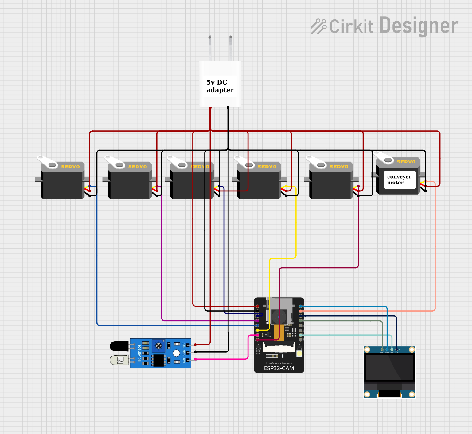

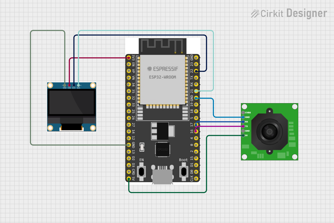
Explore Projects Built with esp cam ov2640
Common Applications and Use Cases
- Wireless video surveillance systems
- Smart home automation (e.g., doorbell cameras, baby monitors)
- IoT-based image recognition and processing
- Remote-controlled robots with live video streaming
- Wildlife monitoring and photography
- Educational projects and prototyping
Technical Specifications
Key Technical Details
| Parameter | Specification |
|---|---|
| Manufacturer | ESP |
| Part ID | OV2640 |
| Image Sensor | OV2640 2MP CMOS sensor |
| Microcontroller | ESP32 |
| Resolution | Up to 1600x1200 (UXGA) |
| Wireless Connectivity | Wi-Fi 802.11 b/g/n |
| Operating Voltage | 3.3V |
| Power Consumption | ~160mA (active mode) |
| Interface | UART, SPI, I2C |
| Flash Memory | 4MB (PSRAM) |
| Camera Interface | SCCB (Serial Camera Control Bus) |
| Dimensions | 27mm x 40.5mm |
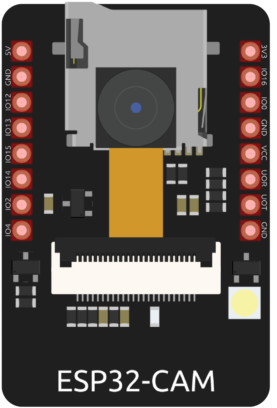
Pin Configuration and Descriptions
| Pin Name | Pin Number | Description |
|---|---|---|
| GND | 1 | Ground connection |
| 3.3V | 2 | Power supply (3.3V input) |
| U0R | 3 | UART RX pin for serial communication |
| U0T | 4 | UART TX pin for serial communication |
| GPIO0 | 5 | GPIO pin for boot mode selection |
| RESET | 6 | Reset pin for the module |
| SDA | 7 | I2C data line for SCCB communication |
| SCL | 8 | I2C clock line for SCCB communication |
| D0-D7 | 9-16 | Data pins for image data transfer |
| VSYNC | 17 | Vertical sync signal |
| HREF | 18 | Horizontal reference signal |
| PCLK | 19 | Pixel clock signal |
Usage Instructions
How to Use the ESP CAM OV2640 in a Circuit
- Power Supply: Connect the 3.3V pin to a stable 3.3V power source and GND to ground.
- UART Communication: Use the U0R and U0T pins to communicate with a microcontroller or computer.
- Boot Mode: Connect GPIO0 to GND during power-up to enter programming mode. Leave it unconnected for normal operation.
- Camera Interface: Use the SCCB (I2C) interface to configure the OV2640 sensor settings.
- Wi-Fi Configuration: Program the ESP32 to connect to a Wi-Fi network for wireless image streaming.
Important Considerations and Best Practices
- Ensure the power supply is stable and does not exceed 3.3V to avoid damaging the module.
- Use a heat sink or proper ventilation if the module operates for extended periods, as the ESP32 can generate heat.
- When programming the ESP32, ensure GPIO0 is grounded to enable flashing mode.
- Use decoupling capacitors near the power pins to reduce noise and improve stability.
- Avoid exposing the camera lens to direct sunlight for prolonged periods to prevent damage.
Example Code for Arduino UNO
Below is an example of how to use the ESP CAM OV2640 with an Arduino IDE to capture and stream images:
#include <WiFi.h>
#include <esp_camera.h>

// Replace with your Wi-Fi credentials
const char* ssid = "Your_SSID";
const char* password = "Your_PASSWORD";

// Camera configuration
#define PWDN_GPIO_NUM    -1
#define RESET_GPIO_NUM   -1
#define XCLK_GPIO_NUM    0
#define SIOD_GPIO_NUM    26
#define SIOC_GPIO_NUM    27
#define Y9_GPIO_NUM      35
#define Y8_GPIO_NUM      34
#define Y7_GPIO_NUM      39
#define Y6_GPIO_NUM      36
#define Y5_GPIO_NUM      21
#define Y4_GPIO_NUM      19
#define Y3_GPIO_NUM      18
#define Y2_GPIO_NUM      5
#define VSYNC_GPIO_NUM   25
#define HREF_GPIO_NUM    23
#define PCLK_GPIO_NUM    22

void setup() {
  Serial.begin(115200);

  // Connect to Wi-Fi
  WiFi.begin(ssid, password);
  while (WiFi.status() != WL_CONNECTED) {
    delay(500);
    Serial.print(".");
  }
  Serial.println("\nWi-Fi connected");

  // Initialize the camera
  camera_config_t config;
  config.ledc_channel = LEDC_CHANNEL_0;
  config.ledc_timer = LEDC_TIMER_0;
  config.pin_d0 = Y2_GPIO_NUM;
  config.pin_d1 = Y3_GPIO_NUM;
  config.pin_d2 = Y4_GPIO_NUM;
  config.pin_d3 = Y5_GPIO_NUM;
  config.pin_d4 = Y6_GPIO_NUM;
  config.pin_d5 = Y7_GPIO_NUM;
  config.pin_d6 = Y8_GPIO_NUM;
  config.pin_d7 = Y9_GPIO_NUM;
  config.pin_xclk = XCLK_GPIO_NUM;
  config.pin_pclk = PCLK_GPIO_NUM;
  config.pin_vsync = VSYNC_GPIO_NUM;
  config.pin_href = HREF_GPIO_NUM;
  config.pin_sscb_sda = SIOD_GPIO_NUM;
  config.pin_sscb_scl = SIOC_GPIO_NUM;
  config.pin_pwdn = PWDN_GPIO_NUM;
  config.pin_reset = RESET_GPIO_NUM;
  config.xclk_freq_hz = 20000000;
  config.pixel_format = PIXFORMAT_JPEG;

  if (esp_camera_init(&config) != ESP_OK) {
    Serial.println("Camera initialization failed");
    return;
  }
  Serial.println("Camera initialized successfully");
}

void loop() {
  // Capture an image
  camera_fb_t* fb = esp_camera_fb_get();
  if (!fb) {
    Serial.println("Failed to capture image");
    return;
  }

  // Print image size
  Serial.printf("Captured image size: %d bytes\n", fb->len);

  // Return the frame buffer to the driver
  esp_camera_fb_return(fb);

  delay(5000); // Wait 5 seconds before capturing the next image
}
Troubleshooting and FAQs
Common Issues and Solutions
Camera Initialization Failed:
- Ensure the camera is properly connected to the ESP32.
- Verify the pin configuration in the code matches your hardware setup.
- Check the power supply voltage (must be 3.3V).
Wi-Fi Connection Issues:
- Double-check the SSID and password in the code.
- Ensure the Wi-Fi network is within range and operational.
Image Quality is Poor:
- Clean the camera lens to remove dust or smudges.
- Adjust the resolution and compression settings in the code.
Module Overheating:
- Use a heat sink or ensure proper ventilation.
- Reduce the operating time or duty cycle.
FAQs
Can the ESP CAM OV2640 record video? Yes, it can stream video over Wi-Fi, but recording requires additional storage or a connected device.
What is the maximum resolution supported? The OV2640 sensor supports up to 1600x1200 (UXGA) resolution.
Can I use this module with a 5V power supply? No, the module operates at 3.3V. Using 5V can damage the components.
Is the module compatible with Arduino IDE? Yes, the ESP CAM OV2640 can be programmed using the Arduino IDE with the appropriate ESP32 board package installed.