
How to Use SMPS : Examples, Pinouts, and Specs
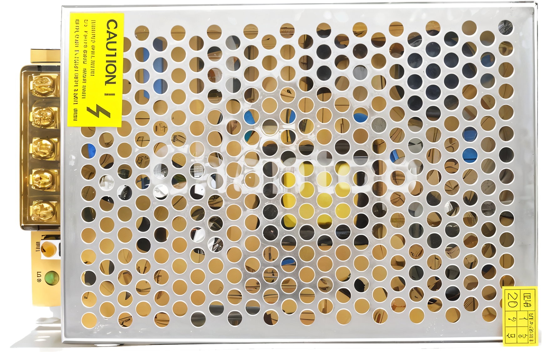
 Design with SMPS in Cirkit Designer
Introduction
A Switch Mode Power Supply (SMPS) is an electronic power supply that utilizes a switching regulator to efficiently convert electrical power. Unlike linear power supplies, SMPS achieves high efficiency by rapidly switching on and off, minimizing energy loss. It is widely used in applications requiring compact, lightweight, and energy-efficient power solutions.
Explore Projects Built with SMPS
 Open Project in Cirkit Designer
 Open Project in Cirkit Designer
 Open Project in Cirkit Designer
 Open Project in Cirkit Designer
Explore Projects Built with SMPS
Open Project in Cirkit DesignerOpen Project in Cirkit DesignerOpen Project in Cirkit DesignerOpen Project in Cirkit DesignerCommon Applications and Use Cases
- Powering consumer electronics (e.g., TVs, computers, and gaming consoles)
- Industrial automation systems
- Battery charging circuits
- LED lighting systems
- Telecommunications equipment
- Medical devices
Technical Specifications
Below are the general technical specifications for an SMPS. Note that specific values may vary depending on the model and manufacturer.
Key Technical Details
- Input Voltage Range: 85V AC to 265V AC (universal input)
- Output Voltage: 3.3V DC, 5V DC, 12V DC, 24V DC, or custom
- Output Current: 0.5A to 50A (depending on the model)
- Efficiency: Typically 80% to 95%
- Switching Frequency: 20 kHz to 1 MHz
- Ripple and Noise: <1% of output voltage
- Operating Temperature: -20°C to +70°C
- Protection Features: Overvoltage, overcurrent, short circuit, and thermal protection
Pin Configuration and Descriptions
The SMPS typically has input and output terminals. Below is a general pin configuration:
| Pin Name | Description |
|---|---|
| AC-L | Live AC input (85V AC to 265V AC) |
| AC-N | Neutral AC input |
| GND | Ground connection for DC output |
| VOUT+ | Positive DC output |
| VOUT- | Negative DC output |
For models with additional features, such as remote control or feedback, extra pins may be present.
Usage Instructions
How to Use the SMPS in a Circuit
Input Connection:
- Connect the AC-L and AC-N terminals to the live and neutral wires of the AC mains supply.
- Ensure proper insulation and safety precautions when handling high-voltage AC inputs.
Output Connection:
- Connect the VOUT+ and VOUT- terminals to the load requiring DC power.
- Verify that the load's voltage and current requirements match the SMPS output specifications.
Grounding:
- Connect the GND terminal to the system ground to ensure proper operation and safety.
Mounting:
- Secure the SMPS in a well-ventilated area to prevent overheating.
- Avoid placing the SMPS near heat-sensitive components.
Important Considerations and Best Practices
- Load Matching: Ensure the load does not exceed the SMPS's rated output current.
- Heat Dissipation: Use proper heat sinks or cooling mechanisms if the SMPS operates at high power levels.
- EMI/EMC Compliance: Use appropriate filters to minimize electromagnetic interference.
- Safety: Always disconnect the SMPS from the mains supply before making any connections or adjustments.
Example: Using an SMPS with Arduino UNO
To power an Arduino UNO using a 5V DC SMPS:
- Connect the VOUT+ terminal of the SMPS to the Arduino's 5V pin.
- Connect the VOUT- terminal of the SMPS to the Arduino's GND pin.
- Ensure the SMPS output is stable and within the Arduino's voltage tolerance.
Here is a simple Arduino code example to blink an LED while powered by the SMPS:
// Blink an LED connected to pin 13 of the Arduino UNO
// Ensure the Arduino is powered by a 5V DC SMPS

void setup() {
  pinMode(13, OUTPUT); // Set pin 13 as an output pin
}

void loop() {
  digitalWrite(13, HIGH); // Turn the LED on
  delay(1000);            // Wait for 1 second
  digitalWrite(13, LOW);  // Turn the LED off
  delay(1000);            // Wait for 1 second
}
Troubleshooting and FAQs
Common Issues and Solutions
No Output Voltage:
- Check the AC input connections and ensure the mains supply is active.
- Verify that the SMPS is not in protection mode due to overcurrent or short circuit.
Overheating:
- Ensure proper ventilation and cooling.
- Check if the load exceeds the SMPS's rated power.
High Ripple or Noise:
- Add a capacitor or LC filter at the output to reduce ripple.
- Verify that the load is stable and not causing fluctuations.
Interference with Other Devices:
- Use EMI filters on the input and output lines.
- Ensure proper grounding and shielding.
FAQs
Q1: Can I use an SMPS to power sensitive electronics?
A1: Yes, but ensure the SMPS has low ripple and noise. Adding additional filtering may help.
Q2: What happens if I exceed the rated output current?
A2: The SMPS will typically enter protection mode or shut down to prevent damage.
Q3: Can I use an SMPS with a battery?
A3: Yes, but ensure the SMPS output voltage matches the battery's charging requirements.
Q4: Is it safe to touch the SMPS while in operation?
A4: No, avoid touching the SMPS during operation, especially the input side, as it involves high voltage.
By following these guidelines, you can safely and effectively use an SMPS in your electronic projects.