How to Use yellow led: Examples, Pinouts, and Specs
Introduction
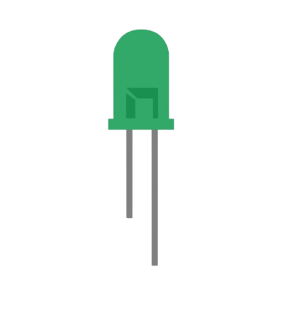
The Yellow LED (Light Emitting Diode) manufactured by Lina with part ID 1 is a semiconductor device that emits yellow light when an electric current flows through it. This component is widely used in electronic circuits for visual indicators, status displays, and decorative lighting. Its low power consumption, long lifespan, and reliability make it an essential component in various applications.
Explore Projects Built with yellow led
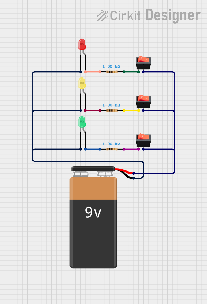
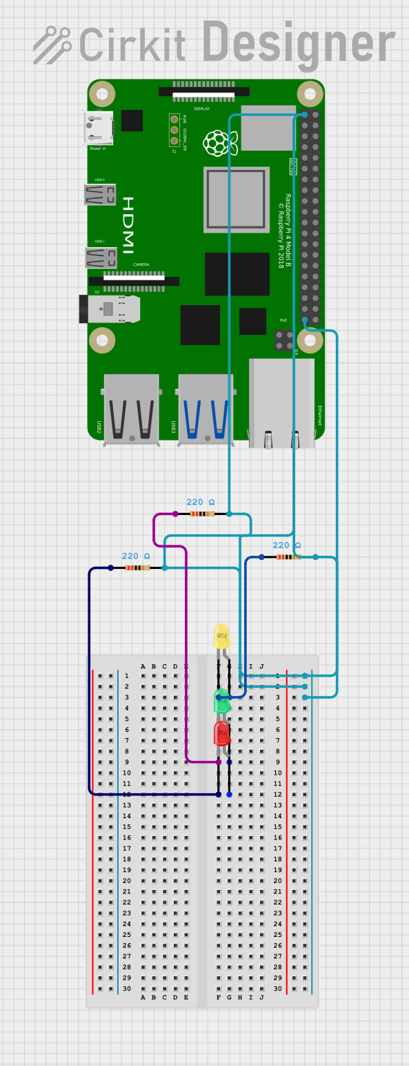
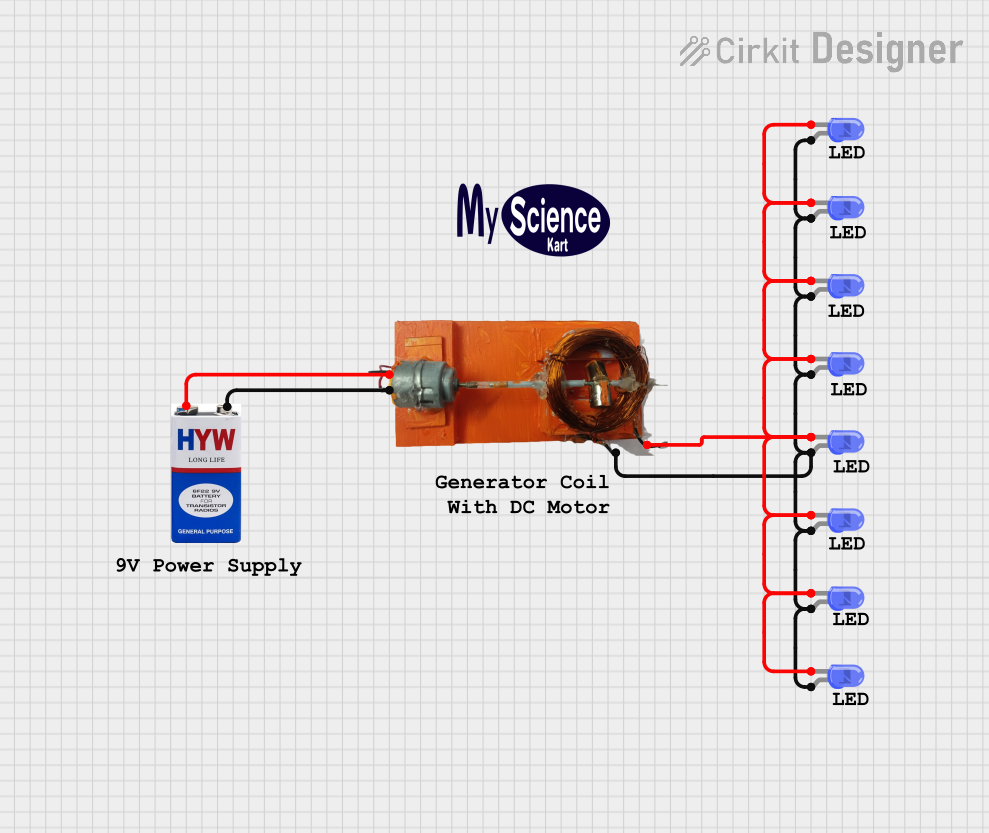

Explore Projects Built with yellow led
Common Applications
- Power and status indicators in electronic devices
- Signal and warning lights
- Decorative and ambient lighting
- Educational and DIY electronics projects
- Displays in consumer electronics
Technical Specifications
Below are the key technical details for the Lina Yellow LED (Part ID: 1):
| Parameter | Value |
|---|---|
| Forward Voltage (Vf) | 2.0V to 2.2V |
| Forward Current (If) | 20mA (typical) |
| Maximum Current (If max) | 30mA |
| Wavelength | 590nm (yellow light) |
| Viewing Angle | 30° to 60° |
| Power Dissipation | 60mW |
| Operating Temperature | -40°C to +85°C |
| Storage Temperature | -40°C to +100°C |
Pin Configuration
The Yellow LED has two pins:
| Pin Name | Description |
|---|---|
| Anode (+) | Positive terminal; connect to power supply or resistor. |
| Cathode (-) | Negative terminal; connect to ground. |
Note: The longer leg of the LED is the anode (+), and the shorter leg is the cathode (-). If the legs are trimmed, the flat edge on the LED casing indicates the cathode.
Usage Instructions
How to Use the Yellow LED in a Circuit
Determine the Resistor Value: To prevent damage, always use a current-limiting resistor in series with the LED. The resistor value can be calculated using Ohm's Law: [ R = \frac{V_{supply} - V_f}{I_f} ] Where:
- ( V_{supply} ) is the supply voltage.
- ( V_f ) is the forward voltage of the LED (2.0V to 2.2V).
- ( I_f ) is the desired forward current (typically 20mA).
For example, with a 5V supply: [ R = \frac{5V - 2.0V}{0.02A} = 150\Omega ]
Connect the LED:
- Connect the anode (+) to the positive terminal of the power supply through the resistor.
- Connect the cathode (-) to the ground.
Test the Circuit: Power the circuit and observe the yellow light emitted by the LED.
Important Considerations
- Polarity: LEDs are polarized components. Reversing the polarity may prevent the LED from lighting up or damage it.
- Current Limiting: Always use a resistor to limit the current through the LED. Exceeding the maximum current rating can permanently damage the LED.
- Heat Management: Ensure the LED operates within its specified temperature range to avoid performance degradation.
Example: Connecting a Yellow LED to an Arduino UNO
Below is an example of how to connect and control a Yellow LED using an Arduino UNO:
Circuit Diagram
- Connect the anode (+) of the LED to Arduino pin 9 through a 220Ω resistor.
- Connect the cathode (-) of the LED to the Arduino GND pin.
Arduino Code
// Example code to blink a Yellow LED connected to pin 9 of Arduino UNO

const int ledPin = 9; // Pin connected to the Yellow LED

void setup() {
  pinMode(ledPin, OUTPUT); // Set pin 9 as an output
}

void loop() {
  digitalWrite(ledPin, HIGH); // Turn the LED on
  delay(1000);                // Wait for 1 second
  digitalWrite(ledPin, LOW);  // Turn the LED off
  delay(1000);                // Wait for 1 second
}
Note: Adjust the resistor value based on your power supply voltage to ensure safe operation.
Troubleshooting and FAQs
Common Issues
LED Does Not Light Up:
- Cause: Incorrect polarity.
- Solution: Ensure the anode (+) is connected to the positive voltage and the cathode (-) to ground.
LED is Dim:
- Cause: Resistor value too high.
- Solution: Recalculate the resistor value to allow more current (but within the LED's limits).
LED Burns Out:
- Cause: Excessive current due to missing or incorrect resistor.
- Solution: Always use a current-limiting resistor and verify its value.
Flickering LED:
- Cause: Unstable power supply or loose connections.
- Solution: Check the power supply and ensure all connections are secure.
FAQs
Q: Can I connect the LED directly to a 3.3V or 5V power supply?
A: No, always use a current-limiting resistor to prevent damage to the LED.Q: How do I identify the anode and cathode if the legs are trimmed?
A: Look for the flat edge on the LED casing, which indicates the cathode (-).Q: Can I use the Yellow LED for PWM dimming?
A: Yes, the brightness of the LED can be controlled using PWM (Pulse Width Modulation) from a microcontroller like Arduino.
By following this documentation, you can effectively use the Lina Yellow LED (Part ID: 1) in your projects with confidence!