How to Use LIN to TTL: Examples, Pinouts, and Specs
Introduction
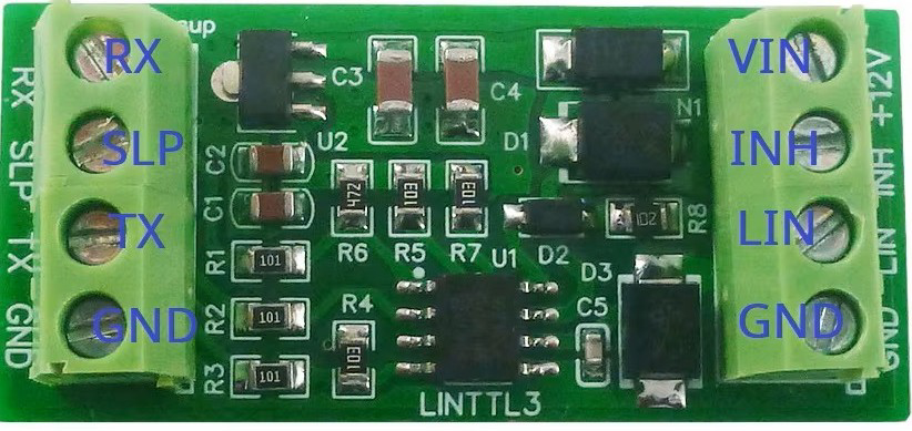
The LIN to TTL Converter (TJA1020), manufactured by LINTTL3, is a device designed to translate Local Interconnect Network (LIN) signals to Transistor-Transistor Logic (TTL) levels. This enables seamless communication between LIN devices and TTL-compatible systems, such as microcontrollers or UART-based devices. The TJA1020 is widely used in automotive and industrial applications where LIN communication is required to interface with TTL-based systems.
Explore Projects Built with LIN to TTL

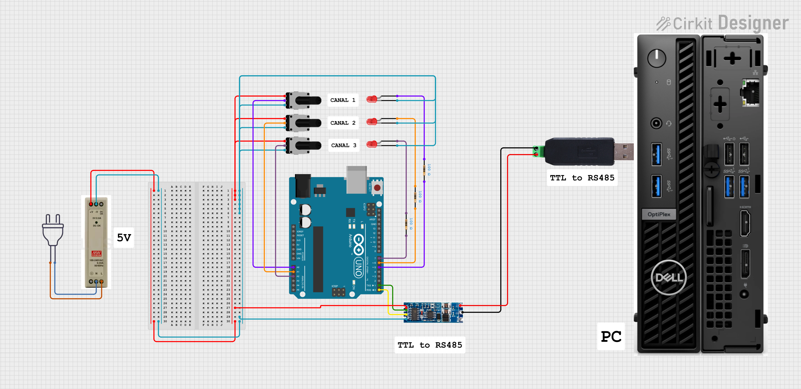

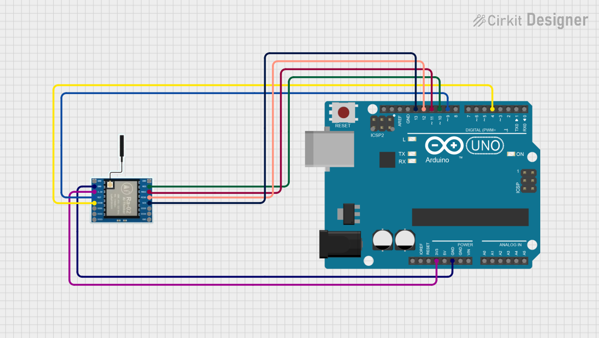
Explore Projects Built with LIN to TTL
Common Applications and Use Cases
- Automotive systems for interfacing LIN buses with microcontrollers
- Industrial automation and control systems
- Home automation devices using LIN communication
- Prototyping and testing LIN-based communication systems
- Bridging LIN networks to UART or TTL-compatible devices
Technical Specifications
Key Technical Details
| Parameter | Value |
|---|---|
| Manufacturer | LINTTL3 |
| Part ID | TJA1020 |
| Supply Voltage (Vcc) | 5V ± 0.5V |
| LIN Bus Voltage Range | -27V to +40V |
| TTL Output Voltage Levels | 0V (Low) to 5V (High) |
| Baud Rate | Up to 20 kbps |
| Operating Temperature | -40°C to +125°C |
| Power Consumption | Low power standby mode available |
| Package Type | SO8 (Small Outline Package) |
Pin Configuration and Descriptions
The TJA1020 comes in an 8-pin SO8 package. Below is the pinout and description:
| Pin Number | Pin Name | Description |
|---|---|---|
| 1 | TXD | TTL input for transmitting data to the LIN bus |
| 2 | GND | Ground connection |
| 3 | VCC | Power supply input (5V) |
| 4 | RXD | TTL output for receiving data from the LIN bus |
| 5 | EN | Enable pin to activate or deactivate the transceiver |
| 6 | LIN | LIN bus connection |
| 7 | WAKE | Wake-up input to bring the device out of low-power standby mode |
| 8 | N.C. | Not connected (reserved for future use) |
Usage Instructions
How to Use the Component in a Circuit
- Power Supply: Connect the VCC pin to a regulated 5V power supply and the GND pin to the ground of your circuit.
- LIN Bus Connection: Connect the LIN pin to the LIN bus line in your system.
- TTL Communication:
- Connect the TXD pin to the microcontroller's UART TX pin for transmitting data.
- Connect the RXD pin to the microcontroller's UART RX pin for receiving data.
- Enable the Transceiver: Pull the EN pin high (5V) to activate the transceiver. Pull it low (0V) to deactivate it.
- Wake-Up Functionality: If the device is in low-power standby mode, apply a high signal to the WAKE pin to bring it back to active mode.
Important Considerations and Best Practices
- Voltage Levels: Ensure that the VCC supply is stable and within the specified range (5V ± 0.5V).
- Pull-Up Resistor: Use a pull-up resistor (typically 1kΩ to 10kΩ) on the LIN bus line as required by the LIN specification.
- Decoupling Capacitor: Place a 100nF decoupling capacitor close to the VCC pin to filter out noise.
- Signal Integrity: Keep the LIN bus line as short as possible to minimize signal degradation.
- Standby Mode: Use the EN and WAKE pins to manage power consumption effectively in low-power applications.
Example Code for Arduino UNO
Below is an example of how to interface the TJA1020 with an Arduino UNO for basic LIN-to-TTL communication:
// Example code for interfacing TJA1020 LIN to TTL converter with Arduino UNO
// This code demonstrates sending and receiving data over the LIN bus

#define TXD_PIN 2  // Arduino pin connected to TJA1020 TXD
#define RXD_PIN 3  // Arduino pin connected to TJA1020 RXD
#define EN_PIN 4   // Arduino pin connected to TJA1020 EN (Enable)

void setup() {
  pinMode(EN_PIN, OUTPUT);  // Set EN pin as output
  digitalWrite(EN_PIN, HIGH);  // Enable the TJA1020 transceiver

  Serial.begin(9600);  // Initialize UART communication at 9600 baud
  Serial.println("TJA1020 LIN to TTL Converter Initialized");
}

void loop() {
  // Send data to the LIN bus
  Serial.println("Sending data to LIN bus...");
  delay(1000);  // Wait for 1 second

  // Check for incoming data from the LIN bus
  if (Serial.available() > 0) {
    String receivedData = Serial.readString();  // Read data from LIN bus
    Serial.print("Received data: ");
    Serial.println(receivedData);
  }
}
Troubleshooting and FAQs
Common Issues and Solutions
| Issue | Possible Cause | Solution |
|---|---|---|
| No communication on the LIN bus | EN pin not activated | Ensure the EN pin is pulled high (5V) to enable the transceiver. |
| Data corruption or noise on the bus | Improper pull-up resistor or long wires | Use a proper pull-up resistor (1kΩ to 10kΩ) and minimize wire length. |
| Device not waking from standby mode | WAKE pin not triggered | Apply a high signal to the WAKE pin to bring the device out of standby. |
| Overheating of the TJA1020 | Incorrect supply voltage | Verify that the VCC supply is within the specified range (5V ± 0.5V). |
FAQs
Can the TJA1020 operate at 3.3V logic levels?
No, the TJA1020 is designed for 5V TTL logic levels. Use a level shifter if interfacing with 3.3V systems.What is the maximum baud rate supported?
The TJA1020 supports baud rates up to 20 kbps, as per the LIN specification.Is the TJA1020 compatible with Arduino?
Yes, the TJA1020 can be easily interfaced with Arduino boards using UART communication.Can I use the TJA1020 for non-automotive applications?
Absolutely! The TJA1020 is suitable for any application requiring LIN-to-TTL conversion.
By following this documentation, you can effectively integrate the TJA1020 LIN to TTL converter into your projects.