
How to Use DC Motor: Examples, Pinouts, and Specs
 Design with DC Motor in Cirkit Designer
Introduction
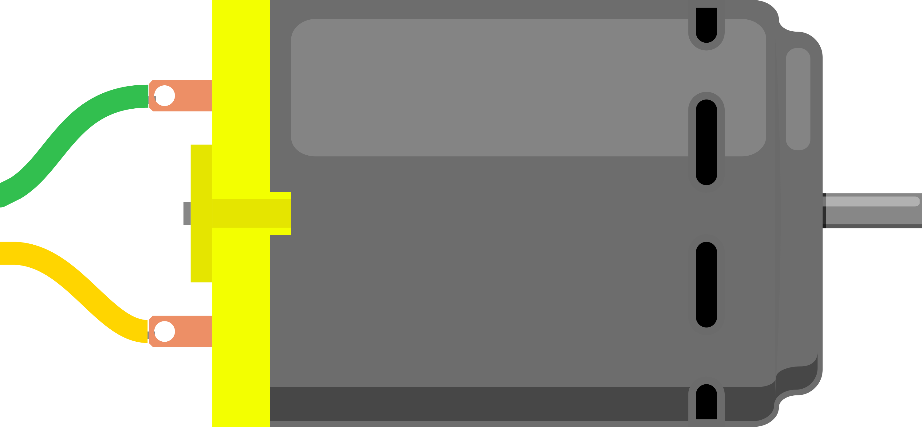
A DC motor is an electromechanical device that converts direct current (DC) electrical energy into mechanical energy. It operates on the principle of electromagnetic induction, where a magnetic field interacts with a current-carrying conductor to produce rotational motion. DC motors are widely used due to their simplicity, reliability, and ability to provide precise speed and torque control.
Explore Projects Built with DC Motor
 Open Project in Cirkit Designer
 Open Project in Cirkit Designer
 Open Project in Cirkit Designer
 Open Project in Cirkit Designer
Explore Projects Built with DC Motor
Open Project in Cirkit DesignerOpen Project in Cirkit DesignerOpen Project in Cirkit DesignerOpen Project in Cirkit DesignerCommon Applications and Use Cases
- Robotics: Driving wheels, arms, and other moving parts.
- Industrial Machinery: Conveyor belts, pumps, and fans.
- Consumer Electronics: Toys, small appliances, and electric tools.
- Automotive: Windshield wipers, power windows, and electric vehicle propulsion.
Technical Specifications
Below are the general technical specifications for a typical DC motor. Note that actual values may vary depending on the specific model.
Key Technical Details
- Operating Voltage: 3V to 24V (varies by model)
- Current Rating: 100mA to 2A (depending on load)
- Speed: 1000 to 10,000 RPM (Revolutions Per Minute)
- Torque: 0.1 to 10 Nm (Newton-meters)
- Power Output: 0.1W to 100W
- Motor Type: Brushed or Brushless
Pin Configuration and Descriptions
For a basic brushed DC motor, there are typically two terminals:
| Pin/Terminal | Description |
|---|---|
| Positive (+) | Connects to the positive terminal of the power supply. |
| Negative (-) | Connects to the negative terminal of the power supply. |
For brushless DC motors, additional control pins may be present, such as Hall sensor outputs or PWM inputs. Refer to the motor's datasheet for specific details.
Usage Instructions
How to Use the Component in a Circuit
- Power Supply: Connect the motor's positive terminal to the positive output of a DC power supply and the negative terminal to the ground. Ensure the voltage and current ratings match the motor's specifications.
- Motor Driver: Use a motor driver (e.g., L298N or L293D) to control the motor's speed and direction. Directly connecting the motor to a microcontroller is not recommended due to high current requirements.
- Control Signal: For speed control, use a Pulse Width Modulation (PWM) signal from a microcontroller like an Arduino.
Important Considerations and Best Practices
- Current Protection: Use a fuse or current-limiting resistor to prevent damage from overcurrent.
- Heat Dissipation: Ensure proper ventilation or heat sinks to avoid overheating during prolonged use.
- Reverse Polarity: Avoid reversing the polarity unless the motor is designed for bidirectional operation.
- Load Matching: Ensure the motor's torque and speed ratings match the application's requirements.
Example: Controlling a DC Motor with Arduino UNO
Below is an example of controlling a DC motor using an Arduino UNO and an L298N motor driver.
// Arduino code to control a DC motor using PWM and L298N motor driver

// Define motor control pins
const int ENA = 9;  // PWM pin for speed control
const int IN1 = 8;  // Direction control pin 1
const int IN2 = 7;  // Direction control pin 2

void setup() {
  // Set motor control pins as outputs
  pinMode(ENA, OUTPUT);
  pinMode(IN1, OUTPUT);
  pinMode(IN2, OUTPUT);
}

void loop() {
  // Rotate motor in forward direction
  digitalWrite(IN1, HIGH);  // Set IN1 high
  digitalWrite(IN2, LOW);   // Set IN2 low
  analogWrite(ENA, 150);    // Set speed (0-255)

  delay(2000);  // Run motor for 2 seconds

  // Rotate motor in reverse direction
  digitalWrite(IN1, LOW);   // Set IN1 low
  digitalWrite(IN2, HIGH);  // Set IN2 high
  analogWrite(ENA, 150);    // Set speed (0-255)

  delay(2000);  // Run motor for 2 seconds

  // Stop the motor
  digitalWrite(IN1, LOW);   // Set IN1 low
  digitalWrite(IN2, LOW);   // Set IN2 low
  analogWrite(ENA, 0);      // Set speed to 0

  delay(2000);  // Wait for 2 seconds before repeating
}
Troubleshooting and FAQs
Common Issues Users Might Face
Motor Not Spinning:
- Check the power supply voltage and current ratings.
- Verify all connections, especially the motor driver and control pins.
- Ensure the motor is not mechanically jammed.
Overheating:
- Reduce the load on the motor.
- Check for proper ventilation or add a heat sink.
Erratic Speed or Direction:
- Verify the PWM signal from the microcontroller.
- Check for loose or faulty connections.
Noisy Operation:
- Inspect the motor for worn-out brushes (for brushed motors).
- Add capacitors across the motor terminals to reduce electrical noise.
Solutions and Tips for Troubleshooting
- Use a multimeter to measure voltage and current at the motor terminals.
- Test the motor with a simple power supply to rule out driver or control issues.
- Consult the motor's datasheet for specific troubleshooting guidelines.
By following this documentation, users can effectively integrate and operate a DC motor in their projects while avoiding common pitfalls.