How to Use SiPeed MaixCAM: Examples, Pinouts, and Specs
Introduction
The SiPeed MaixCAM is a compact AI camera module designed for edge computing and machine learning applications. Manufactured by Controller, this module integrates a RISC-V processor and a camera sensor, enabling real-time image capture and processing. Its small form factor and powerful processing capabilities make it ideal for AI-based projects, such as object detection, facial recognition, and smart surveillance systems.
Explore Projects Built with SiPeed MaixCAM


Explore Projects Built with SiPeed MaixCAM
Common Applications and Use Cases
- Object detection and classification
- Facial recognition systems
- Smart home automation
- Robotics and autonomous vehicles
- Industrial monitoring and quality control
- Educational projects in AI and machine learning
Technical Specifications
The SiPeed MaixCAM is a feature-rich module with the following key specifications:
| Specification | Details |
|---|---|
| Processor | RISC-V K210 dual-core 64-bit processor with FPU |
| Camera Sensor | OV2640 (2MP) or GC0328 (0.3MP), depending on the variant |
| RAM | 8 MB SRAM |
| Flash Memory | 16 MB NOR Flash |
| Operating Voltage | 5V (via USB) |
| Communication Interfaces | UART, SPI, I2C, GPIO |
| AI Acceleration | Built-in KPU (Kendryte Processing Unit) for neural network acceleration |
| Dimensions | 30mm x 30mm |
| Weight | ~5g |
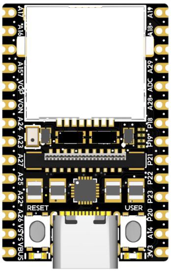
Pin Configuration and Descriptions
The SiPeed MaixCAM features a 24-pin header for interfacing. Below is the pinout:
| Pin Number | Pin Name | Description |
|---|---|---|
| 1 | VCC | Power input (5V) |
| 2 | GND | Ground |
| 3 | TX | UART Transmit |
| 4 | RX | UART Receive |
| 5 | SCL | I2C Clock |
| 6 | SDA | I2C Data |
| 7 | SPI_CS | SPI Chip Select |
| 8 | SPI_CLK | SPI Clock |
| 9 | SPI_MOSI | SPI Master Out Slave In |
| 10 | SPI_MISO | SPI Master In Slave Out |
| 11 | GPIO0 | General Purpose Input/Output |
| 12 | GPIO1 | General Purpose Input/Output |
| 13 | GPIO2 | General Purpose Input/Output |
| 14 | GPIO3 | General Purpose Input/Output |
| 15 | BOOT | Boot mode selection |
| 16 | RST | Reset |
| 17-24 | NC | Not Connected |
Usage Instructions
How to Use the SiPeed MaixCAM in a Circuit
- Powering the Module: Connect the VCC pin to a 5V power source and GND to ground.
- Communication: Use UART, SPI, or I2C interfaces to communicate with the module. For example:
- UART for serial communication with a microcontroller or PC.
- SPI for high-speed data transfer.
- I2C for connecting multiple devices on the same bus.
- Camera Setup: Ensure the camera sensor is properly connected and aligned for image capture.
- Programming: Use the MaixPy IDE or Arduino IDE to program the module. The module supports MicroPython for rapid prototyping.
Important Considerations and Best Practices
- Power Supply: Ensure a stable 5V power supply to avoid performance issues.
- Heat Management: The RISC-V processor may generate heat during intensive tasks. Consider adding a heatsink if necessary.
- Firmware Updates: Regularly update the firmware to access the latest features and bug fixes.
- Camera Lens: Handle the camera lens carefully to avoid scratches or smudges that may affect image quality.
Example Code for Arduino UNO
Below is an example of interfacing the SiPeed MaixCAM with an Arduino UNO via UART:
#include <SoftwareSerial.h>

// Define RX and TX pins for communication with SiPeed MaixCAM
SoftwareSerial maixCamSerial(10, 11); // RX = pin 10, TX = pin 11

void setup() {
  // Initialize serial communication
  Serial.begin(9600); // Communication with PC
  maixCamSerial.begin(115200); // Communication with SiPeed MaixCAM

  Serial.println("Initializing SiPeed MaixCAM...");
  delay(1000);

  // Send a test command to the MaixCAM
  maixCamSerial.println("AT"); // Example command to check communication
}

void loop() {
  // Check if data is available from the MaixCAM
  if (maixCamSerial.available()) {
    String data = maixCamSerial.readString();
    Serial.println("Data from MaixCAM: " + data);
  }

  // Check if data is available from the PC
  if (Serial.available()) {
    String command = Serial.readString();
    maixCamSerial.println(command); // Forward command to MaixCAM
  }
}
Notes:
- Replace
10and11with the appropriate pins on your Arduino UNO. - Ensure the MaixCAM is configured to communicate at 115200 baud rate.
Troubleshooting and FAQs
Common Issues and Solutions
No Response from the Module
- Cause: Incorrect wiring or baud rate mismatch.
- Solution: Double-check the connections and ensure the baud rate matches the module's configuration.
Blurry or No Image Output
- Cause: Dirty or misaligned camera lens.
- Solution: Clean the lens with a microfiber cloth and ensure proper alignment.
Overheating
- Cause: Prolonged use of AI acceleration without proper cooling.
- Solution: Add a heatsink or improve ventilation around the module.
Firmware Update Fails
- Cause: Power interruption or incorrect firmware file.
- Solution: Ensure a stable power supply and use the correct firmware file for your module.
FAQs
Q: Can the SiPeed MaixCAM run TensorFlow Lite models?
A: Yes, the module supports TensorFlow Lite models optimized for the KPU.Q: What is the maximum resolution of the camera?
A: The OV2640 sensor supports up to 1600x1200 resolution, while the GC0328 sensor supports up to 640x480.Q: Can I use the SiPeed MaixCAM with Raspberry Pi?
A: Yes, the module can be interfaced with Raspberry Pi via UART, SPI, or I2C.Q: Is the module compatible with MicroPython?
A: Yes, the SiPeed MaixCAM supports MicroPython for rapid prototyping and development.
This concludes the documentation for the SiPeed MaixCAM. For further assistance, refer to the official datasheet or community forums.