
How to Use Luxeon LED: Examples, Pinouts, and Specs
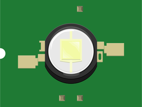
 Design with Luxeon LED in Cirkit Designer
Introduction
The Luxeon LED is a high-performance light-emitting diode (LED) renowned for its exceptional brightness, energy efficiency, and long lifespan. It is designed to deliver superior illumination in a compact form factor, making it ideal for a wide range of applications. Luxeon LEDs are commonly used in general lighting, automotive lighting, display backlighting, and architectural lighting due to their reliability and high luminous output.
Explore Projects Built with Luxeon LED
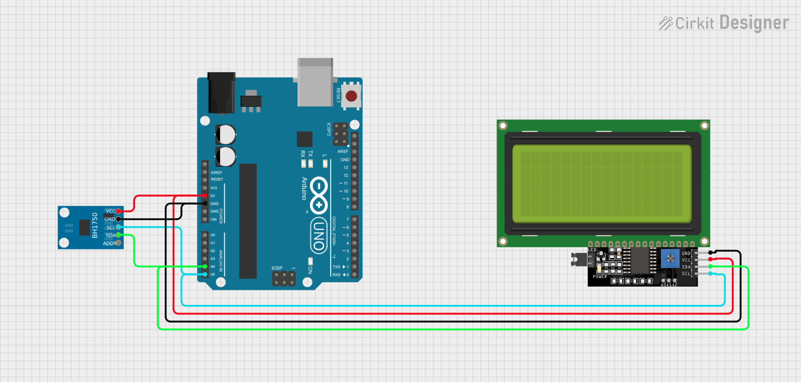 Open Project in Cirkit Designer
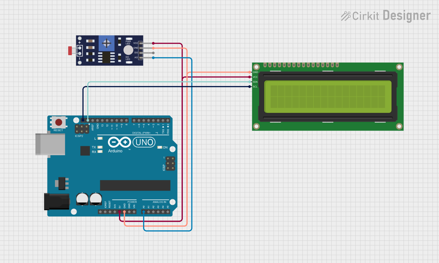 Open Project in Cirkit Designer
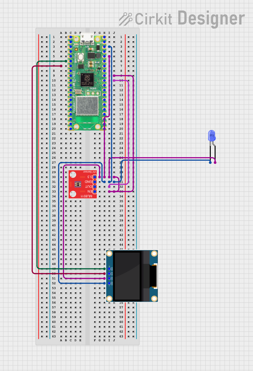 Open Project in Cirkit Designer
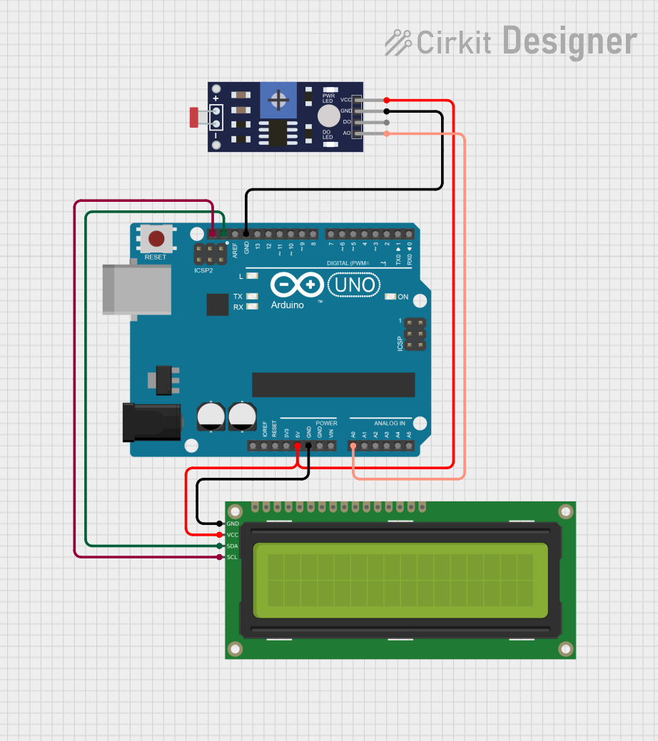 Open Project in Cirkit Designer
Explore Projects Built with Luxeon LED
Open Project in Cirkit DesignerOpen Project in Cirkit DesignerOpen Project in Cirkit DesignerOpen Project in Cirkit DesignerTechnical Specifications
Below are the key technical details for the Luxeon LED. Note that specific values may vary depending on the exact model of the Luxeon LED.
General Specifications
- Forward Voltage (Vf): 2.8V to 3.6V (typical)
- Forward Current (If): 350mA to 1A (depending on model)
- Luminous Flux: 100 to 300 lumens (typical)
- Color Temperature: 2700K to 6500K (for white LEDs)
- Viewing Angle: 120° to 140°
- Thermal Resistance: 2°C/W to 10°C/W
- Operating Temperature Range: -40°C to +85°C
- Lifespan: >50,000 hours (at recommended operating conditions)
Pin Configuration and Descriptions
Luxeon LEDs typically have two pins: an anode (+) and a cathode (-). The table below describes the pin configuration:
| Pin | Name | Description |
|---|---|---|
| 1 | Anode (+) | Positive terminal for forward current |
| 2 | Cathode (-) | Negative terminal for forward current |
Usage Instructions
How to Use the Luxeon LED in a Circuit
Power Supply:
- Ensure the power supply matches the forward voltage and current requirements of the Luxeon LED. Use a constant current driver to prevent overdriving the LED.
Current Limiting Resistor:
- If connecting directly to a power source, calculate and use an appropriate resistor to limit the current. Use Ohm's Law:
[ R = \frac{V_{supply} - V_f}{I_f} ]
where (V_{supply}) is the supply voltage, (V_f) is the forward voltage, and (I_f) is the forward current.
- If connecting directly to a power source, calculate and use an appropriate resistor to limit the current. Use Ohm's Law:
Heat Management:
- Luxeon LEDs generate significant heat. Use a heatsink or thermal pad to dissipate heat and maintain optimal performance.
Polarity:
- Connect the anode (+) to the positive terminal of the power source and the cathode (-) to the negative terminal. Reversing polarity may damage the LED.
Wiring:
- Use appropriate gauge wires to handle the current without excessive resistance or heating.
Example: Connecting Luxeon LED to Arduino UNO
Below is an example of how to control a Luxeon LED using an Arduino UNO and a transistor for current regulation.
Circuit Components:
- Luxeon LED
- NPN transistor (e.g., 2N2222)
- 220-ohm resistor (for Arduino pin to transistor base)
- 10-ohm resistor (for current limiting)
- External 5V power supply
- Arduino UNO
Circuit Diagram:
- Connect the Luxeon LED's anode to the collector of the NPN transistor.
- Connect the cathode of the LED to the negative terminal of the power supply.
- Connect the emitter of the transistor to the negative terminal of the power supply.
- Connect the base of the transistor to an Arduino digital pin (e.g., pin 9) through a 220-ohm resistor.
- Connect the external power supply's positive terminal to the Luxeon LED through a 10-ohm resistor.
Arduino Code:
// Define the pin connected to the transistor base
const int ledPin = 9;

void setup() {
  pinMode(ledPin, OUTPUT); // Set pin 9 as an output
}

void loop() {
  digitalWrite(ledPin, HIGH); // Turn on the Luxeon LED
  delay(1000);               // Keep it on for 1 second
  digitalWrite(ledPin, LOW);  // Turn off the Luxeon LED
  delay(1000);               // Keep it off for 1 second
}
Important Considerations and Best Practices
- Avoid Overdriving: Always use a constant current driver or a properly calculated resistor to prevent overdriving the LED, which can reduce its lifespan.
- Thermal Management: Ensure adequate heat dissipation to maintain performance and prevent damage.
- Polarity Check: Double-check the polarity before powering the LED to avoid irreversible damage.
- Use a Driver Circuit: For high-power Luxeon LEDs, use a dedicated LED driver circuit for optimal performance.
Troubleshooting and FAQs
Common Issues and Solutions
LED Does Not Light Up:
- Cause: Incorrect polarity or insufficient current.
- Solution: Verify the polarity and ensure the power supply provides the required current.
LED Flickers:
- Cause: Unstable power supply or loose connections.
- Solution: Use a stable power source and check all connections.
LED Overheats:
- Cause: Inadequate heat dissipation or overdriving.
- Solution: Add a heatsink or thermal pad and ensure the current is within the recommended range.
Dim Light Output:
- Cause: Insufficient current or degraded LED.
- Solution: Check the current supply and replace the LED if necessary.
FAQs
Q: Can I connect a Luxeon LED directly to a battery?
A: No, you must use a current-limiting resistor or a constant current driver to prevent overdriving the LED.Q: What is the best way to dissipate heat from a Luxeon LED?
A: Use a heatsink or mount the LED on a metal-core printed circuit board (MCPCB) for efficient heat dissipation.Q: Can I dim a Luxeon LED?
A: Yes, you can dim it using pulse-width modulation (PWM) from a microcontroller like an Arduino.Q: What happens if I reverse the polarity?
A: Reversing the polarity can permanently damage the Luxeon LED. Always double-check connections before powering the circuit.