How to Use MAX1555 Lithium Charger IC: Examples, Pinouts, and Specs
Introduction
The MAX1555 is an integrated circuit designed for charging single-cell lithium-ion and lithium-polymer batteries. It is a compact and efficient solution that simplifies the design of battery charging circuits in portable devices. The IC offers features such as automatic current limiting, thermal protection, and reverse-battery protection, making it a reliable choice for maintaining battery health and extending battery life. Common applications include handheld devices, wearable technology, and other small electronics that require a rechargeable power source.
Explore Projects Built with MAX1555 Lithium Charger IC
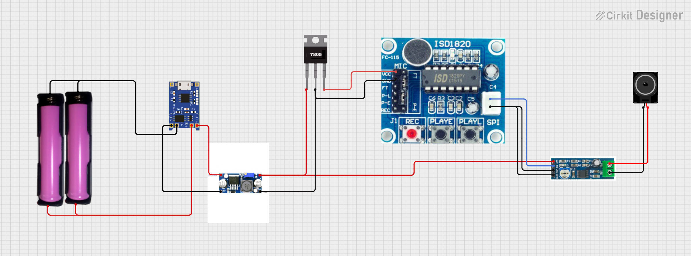
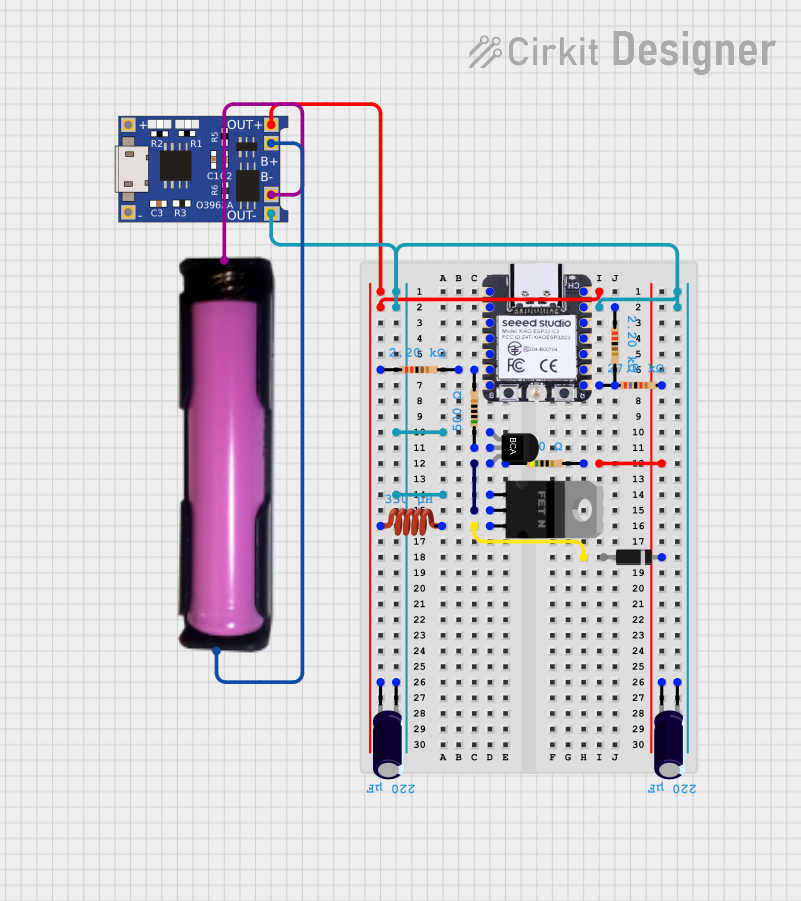


Explore Projects Built with MAX1555 Lithium Charger IC
Technical Specifications
Key Technical Details
- Battery Chemistry: Lithium-Ion/Lithium-Polymer
- Charge Current: Programmable via external resistor (up to 280mA)
- Input Voltage Range: 4.1V to 6.3V
- Thermal Regulation: Prevents overheating
- Charge Indication: LED driver output for charge status
- Protection Features: Reverse-battery, short-circuit, and thermal protection
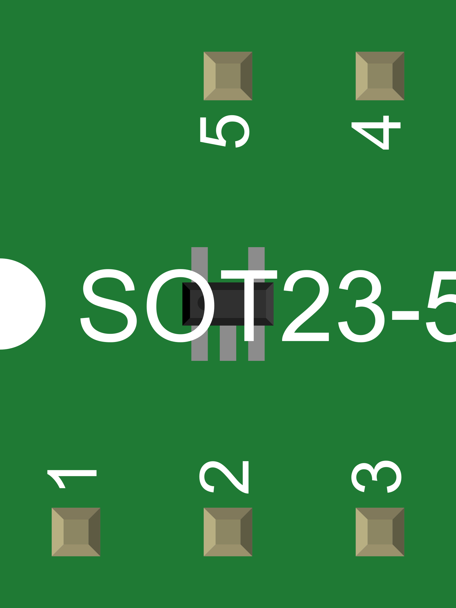
Pin Configuration and Descriptions
| Pin Number | Name | Description |
|---|---|---|
| 1 | GND | Ground connection |
| 2 | BAT | Connection to battery positive terminal |
| 3 | IN | Input voltage from USB or AC adapter |
| 4 | SET | Sets charge current via external resistor |
| 5 | STAT | Open-drain status output to drive an LED |
Usage Instructions
Integrating the MAX1555 into a Circuit
- Power Supply Connection: Connect a stable voltage source (4.1V to 6.3V) to the IN pin.
- Battery Connection: Attach the positive terminal of the lithium battery to the BAT pin. Ensure the battery's negative terminal is connected to the system ground.
- Setting Charge Current: Connect a resistor between the SET pin and GND to program the desired charge current. Refer to the MAX1555 datasheet for the resistor value calculation.
- Charge Status Indicator: Connect an LED and a current-limiting resistor to the STAT pin to provide visual charge status.
Important Considerations and Best Practices
- Ensure that the input voltage does not exceed the specified range to prevent damage to the IC.
- Use a high-quality, stable power source to avoid fluctuations that could affect charging performance.
- Select a proper current-limiting resistor for the LED on the STAT pin to prevent overcurrent damage.
- Place the IC in a location with good airflow to enhance thermal dissipation.
- Always consult the datasheet for detailed information and typical application circuits.
Troubleshooting and FAQs
Common Issues and Solutions
- No Charge Status Indicator: Check the connection and the current-limiting resistor for the LED. Ensure the STAT pin is functioning correctly.
- Battery Not Charging: Verify that the input voltage is within the specified range and that the SET resistor is correctly calculated and installed.
- IC Overheating: Ensure that the thermal limits are not being exceeded and that there is adequate airflow around the IC.
FAQs
Q: Can the MAX1555 charge multiple cells in series? A: No, the MAX1555 is designed for single-cell lithium-ion or lithium-polymer batteries only.
Q: Is an external diode required for reverse-battery protection? A: No, the MAX1555 includes built-in reverse-battery protection.
Q: How can I adjust the charge current? A: The charge current can be adjusted by changing the value of the resistor connected to the SET pin.
Example Arduino UNO Connection and Code
// Example code for interfacing MAX1555 with Arduino UNO
// This code assumes an LED is connected to the STAT pin for charge indication

const int STATpin = 2; // Connect STAT pin of MAX1555 to digital pin 2 on Arduino

void setup() {
  pinMode(STATpin, INPUT); // Set STAT pin as input
  Serial.begin(9600); // Start serial communication at 9600 baud rate
}

void loop() {
  int chargeStatus = digitalRead(STATpin); // Read the charge status from STAT pin

  // Check if the battery is charging or fully charged
  if (chargeStatus == HIGH) {
    Serial.println("Battery is charging...");
  } else {
    Serial.println("Battery is fully charged or not present.");
  }

  delay(1000); // Wait for 1 second before reading the status again
}
Note: This code is for demonstration purposes and does not control the charging process. The MAX1555 handles the charging autonomously based on the external components and connections. The Arduino is used here only to read the charge status from the STAT pin.