How to Use Endstop Switch: Examples, Pinouts, and Specs
Introduction
The Endstop Switch is a mechanical or electronic switch designed to detect the position of a moving part in a system. It is commonly used in 3D printers, CNC machines, and other automated systems to define limits or home positions. By providing feedback to the control system, the Endstop Switch ensures precise movement and prevents mechanical components from exceeding their operational range.
Explore Projects Built with Endstop Switch


Explore Projects Built with Endstop Switch
Common Applications and Use Cases
- 3D Printers: Used to define the home position of the print head or bed.
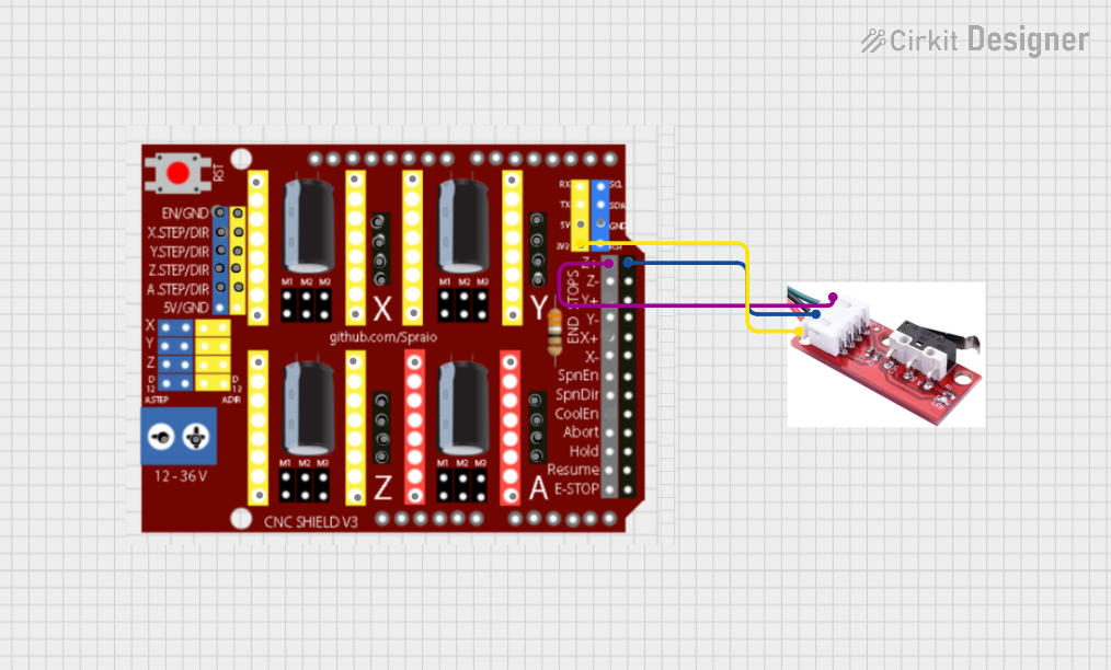
- CNC Machines: Ensures the tool head does not exceed the machine's physical limits.
- Robotics: Detects the end of travel for robotic arms or moving parts.
- Industrial Automation: Monitors and controls the position of conveyor belts or actuators.
Technical Specifications
Key Technical Details
- Type: Mechanical or electronic switch
- Operating Voltage: 5V DC (typical for most applications)
- Current Rating: 300mA (maximum)
- Contact Type: Normally Open (NO) or Normally Closed (NC)
- Switch Life: Up to 1,000,000 cycles (varies by model)
- Mounting: PCB mount or screw mount
- Dimensions: Varies by model, typically compact (e.g., 20mm x 10mm x 5mm)
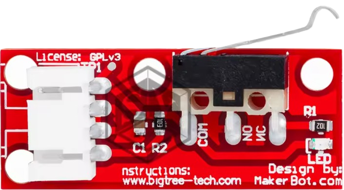
Pin Configuration and Descriptions
The Endstop Switch typically has three pins, though only two are used in most applications. Below is a table describing the pin configuration:
| Pin Name | Description |
|---|---|
| VCC | Power input (5V DC). Supplies power to the switch if it includes an LED. |
| GND | Ground connection. |
| Signal | Output signal pin. Sends a HIGH or LOW signal depending on the switch state. |
Usage Instructions
How to Use the Component in a Circuit
Wiring the Endstop Switch:
- Connect the VCC pin to a 5V power source (if applicable).
- Connect the GND pin to the ground of your circuit.
- Connect the Signal pin to the input pin of your microcontroller or control board.
Configuring the Microcontroller:
- Set the microcontroller pin connected to the Signal pin as an input.
- Use a pull-up or pull-down resistor if required (some switches include built-in resistors).
Testing the Switch:
- When the switch is not pressed, the Signal pin will output a HIGH or LOW signal depending on the configuration.
- When the switch is pressed, the signal will toggle to the opposite state.
Important Considerations and Best Practices
- Debouncing: Mechanical switches may produce noise or multiple signals when toggled. Use software debouncing or a capacitor to filter out false signals.
- Mounting: Ensure the switch is securely mounted to prevent misalignment or damage during operation.
- Wiring: Use proper insulation and strain relief to avoid accidental disconnections.
- Compatibility: Verify the switch's voltage and current ratings match your system requirements.
Example: Connecting to an Arduino UNO
Below is an example of how to connect and use an Endstop Switch with an Arduino UNO:
Circuit Diagram
- VCC: Connect to the Arduino's 5V pin.
- GND: Connect to the Arduino's GND pin.
- Signal: Connect to digital pin 2 on the Arduino.
Code Example
// Define the pin connected to the Endstop Switch
const int endstopPin = 2;

// Variable to store the switch state
int switchState = 0;

void setup() {
  // Initialize the serial monitor for debugging
  Serial.begin(9600);

  // Set the endstop pin as an input with an internal pull-up resistor
  pinMode(endstopPin, INPUT_PULLUP);
}

void loop() {
  // Read the state of the Endstop Switch
  switchState = digitalRead(endstopPin);

  // Print the state to the serial monitor
  if (switchState == LOW) {
    // Switch is pressed
    Serial.println("Endstop triggered!");
  } else {
    // Switch is not pressed
    Serial.println("Endstop not triggered.");
  }

  // Add a small delay to avoid flooding the serial monitor
  delay(100);
}
Troubleshooting and FAQs
Common Issues and Solutions
Switch Not Responding:
- Cause: Incorrect wiring or loose connections.
- Solution: Double-check the wiring and ensure all connections are secure.
False Triggers:
- Cause: Electrical noise or lack of debouncing.
- Solution: Add a capacitor across the switch terminals or implement software debouncing.
Signal Always HIGH or LOW:
- Cause: Faulty switch or incorrect pin configuration.
- Solution: Test the switch with a multimeter and verify the microcontroller pin settings.
LED on Switch Not Lighting Up:
- Cause: Insufficient voltage or damaged LED.
- Solution: Ensure the VCC pin is connected to a 5V source and check the LED with a multimeter.
FAQs
Q: Can I use the Endstop Switch with a 3.3V system?
A: Yes, but ensure the switch is rated for 3.3V operation. If it includes an LED, it may not light up at lower voltages.Q: How do I know if my switch is Normally Open (NO) or Normally Closed (NC)?
A: Use a multimeter to test continuity. In the NO configuration, continuity is established when the switch is pressed. In the NC configuration, continuity is broken when the switch is pressed.Q: Can I use multiple Endstop Switches in one system?
A: Yes, connect each switch to a separate input pin on your microcontroller and configure them individually in your code.Q: Do I need an external pull-up resistor?
A: Most microcontrollers, like the Arduino UNO, have internal pull-up resistors that can be enabled in the code. If your microcontroller does not support this, you may need to add an external resistor.
This documentation provides a comprehensive guide to understanding, using, and troubleshooting the Endstop Switch in various applications.