Cirkit Designer Logo
Cirkit Designer
Your all-in-one circuit design IDE
Home / 
Component Documentation

How to Use Adafruit Ultimate GPS v3: Examples, Pinouts, and Specs

Image of Adafruit Ultimate GPS v3
Cirkit Designer LogoDesign with Adafruit Ultimate GPS v3 in Cirkit Designer

Introduction

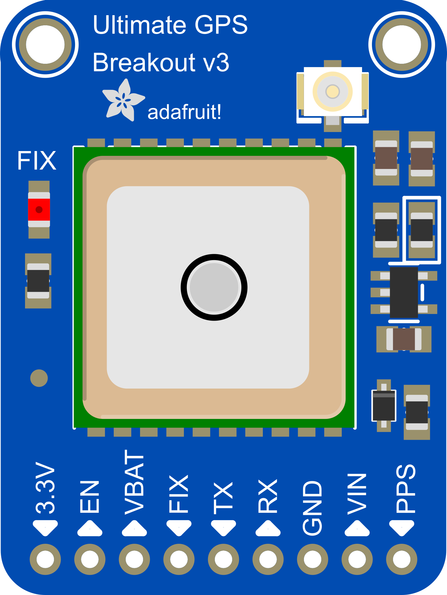
The Adafruit Ultimate GPS v3 is a high-quality GPS module that offers precise location and time data by communicating with GPS satellites. It is designed to be compatible with Arduino boards and other microcontrollers, making it an ideal choice for a wide range of applications such as navigation, time synchronization, and geolocation projects. The module includes a built-in patch antenna, a low-power chipset, and supports multiple communication protocols for easy integration into various systems.

Explore Projects Built with Adafruit Ultimate GPS v3

Use Cirkit Designer to design, explore, and prototype these projects online. Some projects support real-time simulation. Click "Open Project" to start designing instantly!
Arduino UNO Based GPS and GSM Tracking System
Image of priyanka rakshe: A project utilizing Adafruit Ultimate GPS v3 in a practical application
This circuit features an Arduino UNO microcontroller connected to an Adafruit Ultimate GPS v3 module for receiving GPS data. The GPS module is powered by the Arduino's 5V output and communicates via serial connection using the TX and RX pins connected to the Arduino's digital pins D4 and D3, respectively. The microcontroller's code structure is set up with empty setup() and loop() functions, ready for implementing the logic to interact with the GPS module.
Cirkit Designer LogoOpen Project in Cirkit Designer
Arduino UNO Based Multi-Functional Tracking Device with GPS, GSM, and Wi-Fi Capabilities
Image of Accident Detection: A project utilizing Adafruit Ultimate GPS v3 in a practical application
This circuit features an Arduino UNO as the central microcontroller, interfaced with a GPS NEO 6M module for location tracking, an esp8266 nodemcu for WiFi connectivity, and a SIM900A Mini module for GSM communication capabilities. Additionally, it includes an Adafruit ADXL335 accelerometer for motion sensing, and an LCD display for user interface, whose contrast is controlled by a potentiometer. The Arduino is programmed to coordinate these components, likely for a device that requires location tracking, wireless communication, and motion detection with a user-friendly display.
Cirkit Designer LogoOpen Project in Cirkit Designer
ESP32-Based GPS Tracker with OLED Display and Firebase Integration
Image of ecs: A project utilizing Adafruit Ultimate GPS v3 in a practical application
This circuit is a GPS tracking system that uses an ESP32 microcontroller to read location data from a NEO-6M GPS module and display information on a 0.96" OLED screen. The system is powered by a 2000mAh battery with a lithium-ion charger, and it uploads the GPS data to Firebase via WiFi. Additional components include an MPU6050 accelerometer/gyroscope for motion sensing and a buzzer for alerts.
Cirkit Designer LogoOpen Project in Cirkit Designer
Arduino UNO with A9G GSM/GPRS and Dual VL53L1X Distance Sensors
Image of TED CIRCUIT : A project utilizing Adafruit Ultimate GPS v3 in a practical application
This circuit features an Arduino UNO microcontroller interfaced with an A9G GSM/GPRS+GPS/BDS module and two VL53L1X time-of-flight distance sensors. The A9G module is connected to the Arduino via serial communication for GPS and GSM functionalities, while both VL53L1X sensors are connected through I2C with shared SDA and SCL lines and individual SHUT pins for selective sensor activation. The Arduino is programmed to control these peripherals, although the specific functionality is not detailed in the provided code.
Cirkit Designer LogoOpen Project in Cirkit Designer

Explore Projects Built with Adafruit Ultimate GPS v3

Use Cirkit Designer to design, explore, and prototype these projects online. Some projects support real-time simulation. Click "Open Project" to start designing instantly!
Image of priyanka rakshe: A project utilizing Adafruit Ultimate GPS v3 in a practical application
Arduino UNO Based GPS and GSM Tracking System
This circuit features an Arduino UNO microcontroller connected to an Adafruit Ultimate GPS v3 module for receiving GPS data. The GPS module is powered by the Arduino's 5V output and communicates via serial connection using the TX and RX pins connected to the Arduino's digital pins D4 and D3, respectively. The microcontroller's code structure is set up with empty setup() and loop() functions, ready for implementing the logic to interact with the GPS module.
Cirkit Designer LogoOpen Project in Cirkit Designer
Image of Accident Detection: A project utilizing Adafruit Ultimate GPS v3 in a practical application
Arduino UNO Based Multi-Functional Tracking Device with GPS, GSM, and Wi-Fi Capabilities
This circuit features an Arduino UNO as the central microcontroller, interfaced with a GPS NEO 6M module for location tracking, an esp8266 nodemcu for WiFi connectivity, and a SIM900A Mini module for GSM communication capabilities. Additionally, it includes an Adafruit ADXL335 accelerometer for motion sensing, and an LCD display for user interface, whose contrast is controlled by a potentiometer. The Arduino is programmed to coordinate these components, likely for a device that requires location tracking, wireless communication, and motion detection with a user-friendly display.
Cirkit Designer LogoOpen Project in Cirkit Designer
Image of ecs: A project utilizing Adafruit Ultimate GPS v3 in a practical application
ESP32-Based GPS Tracker with OLED Display and Firebase Integration
This circuit is a GPS tracking system that uses an ESP32 microcontroller to read location data from a NEO-6M GPS module and display information on a 0.96" OLED screen. The system is powered by a 2000mAh battery with a lithium-ion charger, and it uploads the GPS data to Firebase via WiFi. Additional components include an MPU6050 accelerometer/gyroscope for motion sensing and a buzzer for alerts.
Cirkit Designer LogoOpen Project in Cirkit Designer
Image of TED CIRCUIT : A project utilizing Adafruit Ultimate GPS v3 in a practical application
Arduino UNO with A9G GSM/GPRS and Dual VL53L1X Distance Sensors
This circuit features an Arduino UNO microcontroller interfaced with an A9G GSM/GPRS+GPS/BDS module and two VL53L1X time-of-flight distance sensors. The A9G module is connected to the Arduino via serial communication for GPS and GSM functionalities, while both VL53L1X sensors are connected through I2C with shared SDA and SCL lines and individual SHUT pins for selective sensor activation. The Arduino is programmed to control these peripherals, although the specific functionality is not detailed in the provided code.
Cirkit Designer LogoOpen Project in Cirkit Designer

Common Applications and Use Cases

  • Personal navigation devices
  • Time synchronization for systems
  • Geolocation tagging for photographs
  • Fleet tracking and management
  • Asset tracking
  • Outdoor sports and recreation
  • UAVs and autonomous vehicles

Technical Specifications

Key Technical Details

  • Voltage: 3.0-5.5V logic and power
  • Current: 20mA during navigation
  • Update Rate: Up to 10 Hz
  • Sensitivity: -165 dBm
  • Operating Temperature: -40°C to 85°C
  • Altitude Limit: 50,000 meters
  • Velocity Limit: 500 m/s
  • Acceleration Limit: Less than 4g

Pin Configuration and Descriptions

Pin Number Name Description
1 VCC Power supply (3.0-5.5V)
2 RX Receive pin for serial communication
3 TX Transmit pin for serial communication
4 GND Ground connection
5 PPS Pulse per second output
6 EN Enable pin for the module

Usage Instructions

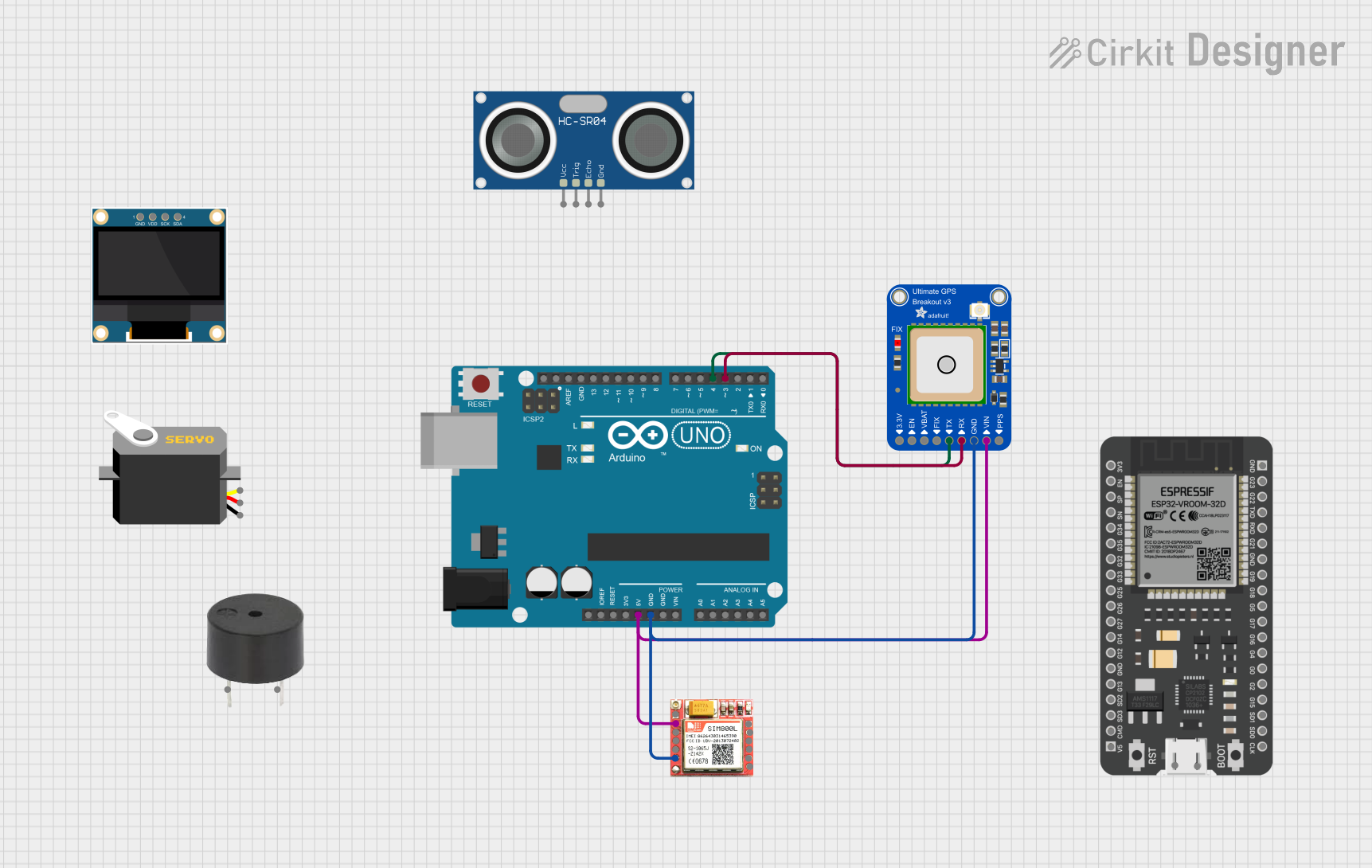
How to Use the Component in a Circuit

  1. Powering the Module: Connect the VCC pin to a 3.0-5.5V power supply and the GND pin to the ground.
  2. Serial Communication: Connect the RX pin to the TX pin of your microcontroller and the TX pin to the RX pin of your microcontroller.
  3. PPS Output: The PPS pin outputs a pulse per second, which can be used for precise timekeeping. This is optional and can be left unconnected if not needed.
  4. Enable Pin: The EN pin can be used to enable or disable the GPS module. Pulling it low will put the module into a low-power state.

Important Considerations and Best Practices

  • Ensure that the GPS module has a clear view of the sky for optimal performance.
  • Avoid placing the module near devices that generate significant electromagnetic interference.
  • Use a level shifter if you are interfacing with a microcontroller that operates at a voltage different from the GPS module's operating voltage.
  • For the best accuracy, allow the GPS module to acquire a fix for a few minutes before using the data.

Example Code for Arduino UNO

#include <Adafruit_GPS.h>
#include <SoftwareSerial.h>

// Connect the GPS TX (transmit) pin to Arduino pin 3
SoftwareSerial mySerial(3, -1);
Adafruit_GPS GPS(&mySerial);

void setup() {
  // Start the serial communication
  Serial.begin(115200);
  GPS.begin(9600);
  
  // Turn on RMC (recommended minimum) and GGA (fix data) including altitude
  GPS.sendCommand(PMTK_SET_NMEA_OUTPUT_RMCGGA);
  
  // Set the update rate
  GPS.sendCommand(PMTK_SET_NMEA_UPDATE_1HZ);
  
  // Request updates on antenna status
  GPS.sendCommand(PGCMD_ANTENNA);
}

void loop() {
  // Read data from the GPS
  char c = GPS.read();
  
  // If a sentence is received, check if it's a valid fix
  if (GPS.newNMEAreceived()) {
    if (!GPS.parse(GPS.lastNMEA())) {
      return;
    }
  }
  
  // If there's a valid fix, print the location and time data
  if (GPS.fix) {
    Serial.print("Location: ");
    Serial.print(GPS.latitude, 4); Serial.print(GPS.lat);
    Serial.print(", ");
    Serial.print(GPS.longitude, 4); Serial.println(GPS.lon);
    
    Serial.print("Time: ");
    Serial.print(GPS.hour, DEC); Serial.print(':');
    Serial.print(GPS.minute, DEC); Serial.print(':');
    Serial.print(GPS.seconds, DEC); Serial.print('.');
    Serial.println(GPS.milliseconds);
    
    Serial.print("Date: ");
    Serial.print(GPS.day, DEC); Serial.print('/');
    Serial.print(GPS.month, DEC); Serial.print("/20");
    Serial.println(GPS.year, DEC);
    
    Serial.print("Fix: "); Serial.println((int)GPS.fix);
    Serial.print("Quality: "); Serial.println((int)GPS.fixquality);
  }
}

Troubleshooting and FAQs

Common Issues

  • No Fix Obtained: Ensure the GPS module has a clear view of the sky. It may take a few minutes to obtain a fix, especially on the first use.
  • Inaccurate Data: Wait for the module to stabilize, as it may take some time to provide accurate readings after powering on.
  • Intermittent Data: Check the serial connections between the GPS module and the microcontroller. Ensure that the baud rate is correctly set.

Solutions and Tips for Troubleshooting

  • Check Power Supply: Verify that the module is receiving the correct voltage.
  • Serial Connection: Ensure that the RX and TX pins are connected to the correct pins on the microcontroller.
  • Antenna Placement: Place the antenna in a location with an unobstructed view of the sky.
  • Cold Start: If the module is taking too long to get a fix, consider performing a cold start command to reset the GPS.

FAQs

Q: How long does it take for the GPS to get a fix? A: It can take anywhere from 30 seconds to several minutes, depending on conditions and whether it's the first time the GPS is acquiring a fix.

Q: Can I use the GPS indoors? A: GPS signals are weak and usually require a clear line of sight to multiple satellites, so indoor use is not recommended.

Q: What is the PPS pin used for? A: The PPS pin outputs a pulse per second, which can be used for precise timing applications.

Q: How can I save power when using the GPS module? A: You can use the EN pin to disable the module when not in use or configure the module to a lower update rate.