
Cirkit Designer
Your all-in-one circuit design IDE
Home /
Component Documentation
How to Use Power: Examples, Pinouts, and Specs
 Design with Power in Cirkit Designer
Introduction
- The power source is a fundamental component in any electronic circuit. It provides the necessary electrical energy in the form of voltage and current to enable the operation of other components in the circuit.
- Common applications include powering microcontrollers, sensors, actuators, and other electronic devices. Power sources can range from batteries and power adapters to regulated power supplies and solar panels.
Explore Projects Built with Power
Battery-Powered UPS with Step-Down Buck Converter and BMS

This circuit is a power management system that steps down a 240V AC input to a lower DC voltage using a buck converter, which then powers a 40W UPS. The UPS is controlled by a rocker switch and is backed up by a battery management system (BMS) connected to three 3.7V batteries in series, ensuring continuous power supply.
Open Project in Cirkit DesignerESP32C3 and SIM800L Powered Smart Energy Monitor with OLED Display and Wi-Fi Connectivity
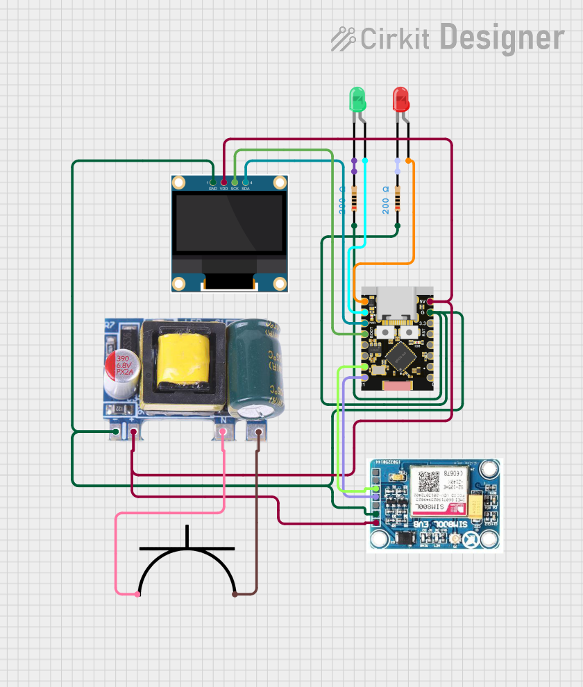
This circuit is a power monitoring system that uses an ESP32C3 microcontroller to collect power usage data from slave devices via WiFi and SMS. The collected data is displayed on a 0.96" OLED screen, and the system is powered by an AC-DC converter module. Additionally, the circuit includes a SIM800L GSM module for SMS communication and LEDs for status indication.
Open Project in Cirkit DesignerAC to DC Power Supply with Transformer and Bridge Rectifier

This circuit is a basic AC to DC power supply that steps down 220V AC to a lower voltage using a transformer, rectifies it to DC using a bridge rectifier made of diodes, and smooths the output with an electrolytic capacitor. A rocker switch is used to turn the power supply on and off.
Open Project in Cirkit DesignerOptiplex Micro and PoE Camera Surveillance System with Ethernet Switching

This circuit describes a networked system where an Optiplex Micro computer is powered by a PC Power Supply and connected to a PC Screen via HDMI for display output. The computer is networked through an Ethernet Switch, which also connects to two PoE Cameras and a Toyopuc PLC. The Ethernet Switch is powered by a PoE PSU 48V DC, and all AC-powered devices are connected to a common 220V AC source.
Open Project in Cirkit DesignerExplore Projects Built with Power
Battery-Powered UPS with Step-Down Buck Converter and BMS
This circuit is a power management system that steps down a 240V AC input to a lower DC voltage using a buck converter, which then powers a 40W UPS. The UPS is controlled by a rocker switch and is backed up by a battery management system (BMS) connected to three 3.7V batteries in series, ensuring continuous power supply.
Open Project in Cirkit DesignerESP32C3 and SIM800L Powered Smart Energy Monitor with OLED Display and Wi-Fi Connectivity
This circuit is a power monitoring system that uses an ESP32C3 microcontroller to collect power usage data from slave devices via WiFi and SMS. The collected data is displayed on a 0.96" OLED screen, and the system is powered by an AC-DC converter module. Additionally, the circuit includes a SIM800L GSM module for SMS communication and LEDs for status indication.
Open Project in Cirkit DesignerAC to DC Power Supply with Transformer and Bridge Rectifier
This circuit is a basic AC to DC power supply that steps down 220V AC to a lower voltage using a transformer, rectifies it to DC using a bridge rectifier made of diodes, and smooths the output with an electrolytic capacitor. A rocker switch is used to turn the power supply on and off.
Open Project in Cirkit DesignerOptiplex Micro and PoE Camera Surveillance System with Ethernet Switching
This circuit describes a networked system where an Optiplex Micro computer is powered by a PC Power Supply and connected to a PC Screen via HDMI for display output. The computer is networked through an Ethernet Switch, which also connects to two PoE Cameras and a Toyopuc PLC. The Ethernet Switch is powered by a PoE PSU 48V DC, and all AC-powered devices are connected to a common 220V AC source.
Open Project in Cirkit DesignerTechnical Specifications
- Key technical details for a power source depend on the specific type being used. Below are general specifications to consider:
- Voltage Range: Typically 1.5V to 48V, depending on the application.
- Current Rating: Varies from milliamps (mA) for small devices to several amps (A) for high-power systems.
- Power Rating: Calculated as Voltage × Current (Watts).
- Regulation: Some power sources provide regulated output to maintain a constant voltage.
- Polarity: Correct polarity (positive and negative terminals) must be observed to avoid damage.
Pin Configuration and Descriptions
The pin configuration for a power source depends on the type of connector or interface used. Below is an example for a DC barrel jack commonly used in electronics:
| Pin Name | Description |
|---|---|
| Positive (+) | Supplies the positive voltage to the circuit. |
| Negative (-) | Provides the ground connection or return path for the current. |
For a USB power source, the pin configuration is as follows:
| Pin Name | Description |
|---|---|
| VBUS | Supplies +5V DC power. |
| GND | Ground connection. |
| D+ | Data line for USB communication (not used for power delivery). |
| D- | Data line for USB communication (not used for power delivery). |
Usage Instructions
How to Use the Component in a Circuit:
- Identify the voltage and current requirements of your circuit.
- Select a power source that matches or exceeds these requirements.
- Connect the positive terminal of the power source to the positive rail of the circuit.
- Connect the negative terminal of the power source to the ground rail of the circuit.
- If using a regulated power supply, adjust the voltage and current settings as needed before powering the circuit.
Important Considerations and Best Practices:
- Always verify the voltage and current ratings of the power source to ensure compatibility with your circuit.
- Use a fuse or circuit breaker to protect against overcurrent conditions.
- For sensitive electronics, consider using a regulated power supply to avoid voltage fluctuations.
- Double-check polarity before connecting the power source to prevent damage to components.
- If using batteries, monitor their charge level to avoid over-discharge, which can damage the batteries.
Example: Connecting a Power Source to an Arduino UNO: The Arduino UNO can be powered via its DC barrel jack or USB port. Below is an example of powering the Arduino UNO with a 9V battery:
// Example code to blink an LED on pin 13 when powered by a 9V battery

void setup() {
  pinMode(13, OUTPUT); // Set pin 13 as an output
}

void loop() {
  digitalWrite(13, HIGH); // Turn the LED on
  delay(1000);            // Wait for 1 second
  digitalWrite(13, LOW);  // Turn the LED off
  delay(1000);            // Wait for 1 second
}
Troubleshooting and FAQs
Common Issues Users Might Face:
- No Power to the Circuit:
- Check the connections to ensure the power source is properly connected.
- Verify that the power source is turned on (if applicable).
- Test the power source with a multimeter to confirm it is outputting the correct voltage.
- Overheating Components:
- Ensure the power source is not supplying excessive voltage or current.
- Check for short circuits in the wiring.
- Voltage Drops or Fluctuations:
- Use a regulated power supply to maintain a stable voltage.
- Ensure the power source has sufficient current capacity for the circuit.
- No Power to the Circuit:
Solutions and Tips for Troubleshooting:
- Use a multimeter to measure voltage and current at various points in the circuit.
- Replace the power source if it is faulty or unable to meet the circuit's requirements.
- For battery-powered circuits, ensure the batteries are fully charged or replace them if depleted.
By following these guidelines, you can effectively use a power source to ensure reliable operation of your electronic circuits.