
How to Use Adafruit ANO Rotary Navigation Encoder Breakout: Examples, Pinouts, and Specs
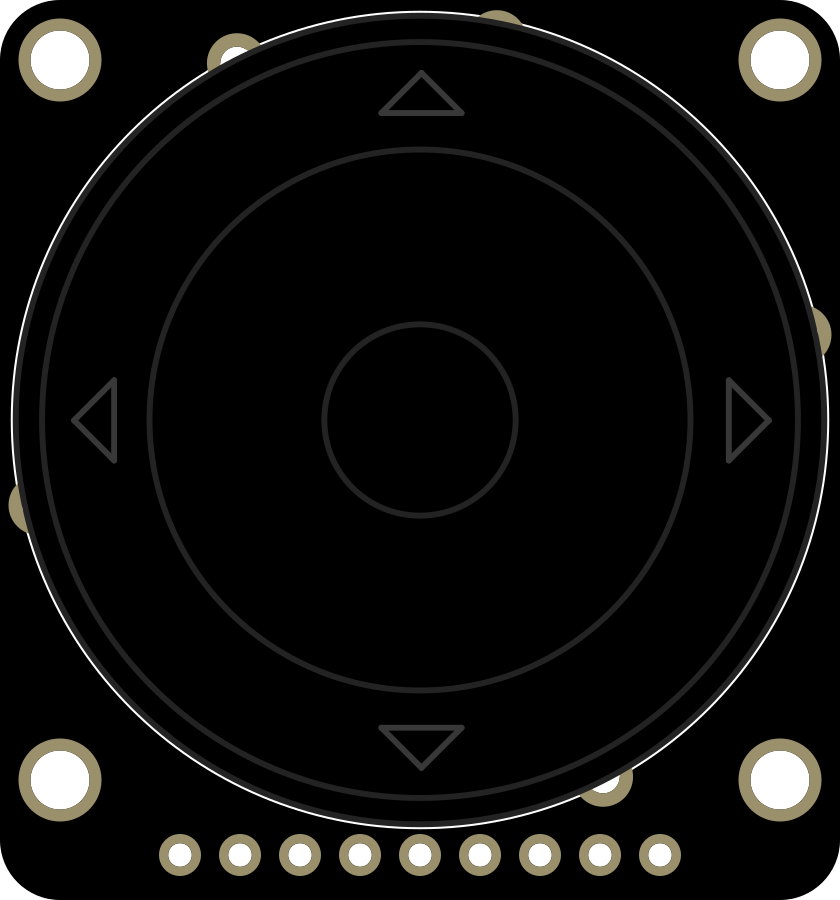
 Design with Adafruit ANO Rotary Navigation Encoder Breakout in Cirkit Designer
Introduction
The Adafruit ANO Rotary Navigation Encoder Breakout is a compact and versatile input device designed for easy navigation and control in electronic projects. This breakout board features a rotary encoder with a built-in push-button, enabling both rotational and press-based input. It is ideal for creating user interfaces, such as menu navigation, volume control, or parameter adjustments in embedded systems.
Explore Projects Built with Adafruit ANO Rotary Navigation Encoder Breakout
 Open Project in Cirkit Designer
 Open Project in Cirkit Designer
 Open Project in Cirkit Designer
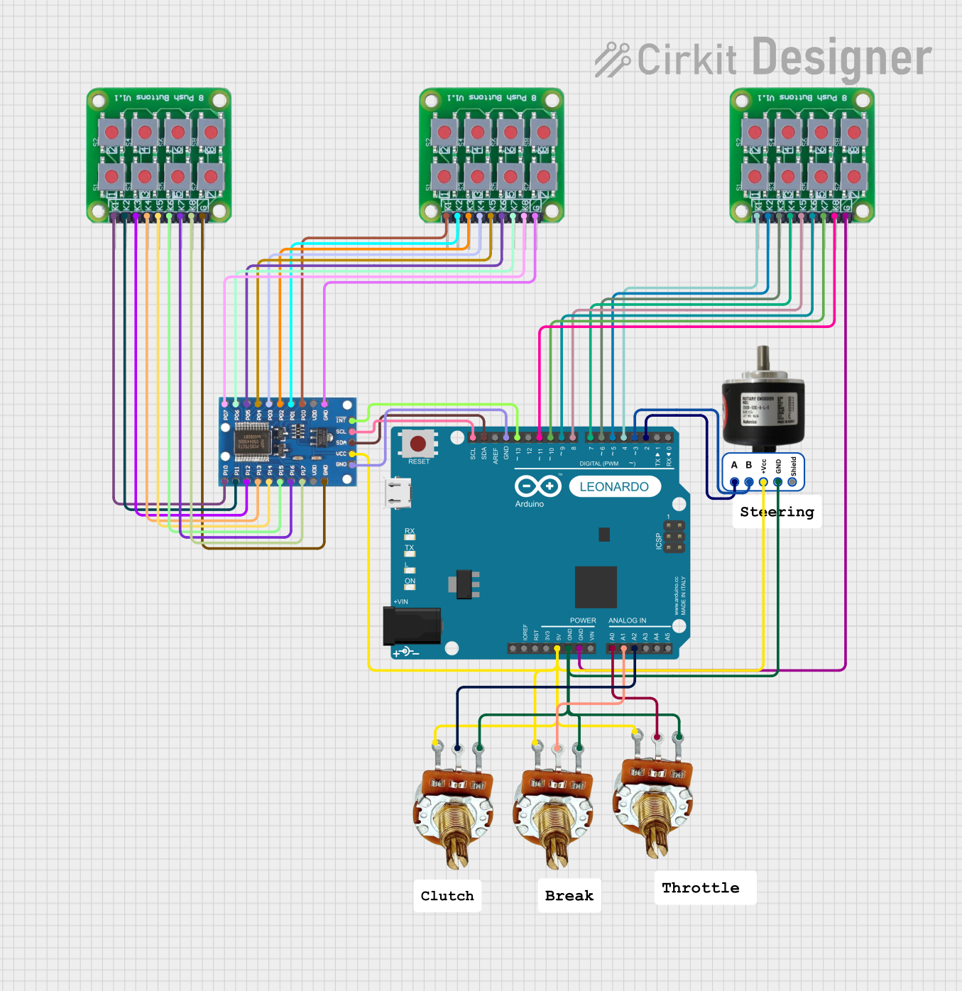 Open Project in Cirkit Designer
Explore Projects Built with Adafruit ANO Rotary Navigation Encoder Breakout
Open Project in Cirkit DesignerOpen Project in Cirkit DesignerOpen Project in Cirkit DesignerOpen Project in Cirkit DesignerCommon Applications and Use Cases
- User interface navigation for embedded systems
- Volume or brightness control in audio/visual devices
- Menu selection in DIY projects
- Input control for robotics and automation systems
- Rotary-based gaming controllers or custom input devices
Technical Specifications
The Adafruit ANO Rotary Navigation Encoder Breakout is designed for ease of use and compatibility with a wide range of microcontrollers, including Arduino boards. Below are the key technical details:
Key Specifications
| Parameter | Value |
|---|---|
| Operating Voltage | 3.3V or 5V |
| Encoder Type | Incremental Rotary Encoder |
| Push-Button Type | Momentary |
| Output Signals | A, B (quadrature signals), and SW |
| Dimensions | 20mm x 20mm x 12mm |
| Mounting Holes | 2 x M2 holes |
Pin Configuration and Descriptions
The breakout board has a 5-pin header for easy connection. Below is the pinout:
| Pin Name | Description |
|---|---|
| GND | Ground connection |
| VCC | Power supply input (3.3V or 5V) |
| A | Quadrature signal A (used for detecting rotation direction and steps) |
| B | Quadrature signal B (used for detecting rotation direction and steps) |
| SW | Push-button signal (active LOW when pressed) |
Usage Instructions
How to Use the Component in a Circuit
- Power the Breakout Board: Connect the
VCCpin to a 3.3V or 5V power source and theGNDpin to ground. - Connect the Encoder Outputs:
- Connect the
AandBpins to digital input pins on your microcontroller to read the rotary encoder's quadrature signals. - Connect the
SWpin to a digital input pin to detect button presses.
- Connect the
- Pull-Up Resistors: The breakout board includes built-in pull-up resistors for the
A,B, andSWpins, so no external resistors are required. - Read the Signals: Use your microcontroller to read the
AandBsignals to determine the direction and number of steps rotated. Monitor theSWpin to detect button presses.
Important Considerations and Best Practices
- Debouncing: Rotary encoders and push-buttons can produce noisy signals. Use software debouncing to ensure accurate readings.
- Signal Timing: Ensure your microcontroller can handle the signal timing of the encoder, especially if it is rotated quickly.
- Mounting: Secure the breakout board using the provided mounting holes to prevent movement during operation.
- Voltage Compatibility: Ensure the
VCCvoltage matches your microcontroller's logic level (3.3V or 5V).
Example Code for Arduino UNO
Below is an example Arduino sketch to read the rotary encoder and push-button signals:
// Define pin connections
const int pinA = 2;  // Connect to encoder pin A
const int pinB = 3;  // Connect to encoder pin B
const int pinSW = 4; // Connect to encoder push-button pin SW

// Variables to track encoder state
int lastStateA;
int currentStateA;
int encoderPosition = 0;

void setup() {
  pinMode(pinA, INPUT_PULLUP); // Enable internal pull-up resistor for pin A
  pinMode(pinB, INPUT_PULLUP); // Enable internal pull-up resistor for pin B
  pinMode(pinSW, INPUT_PULLUP); // Enable internal pull-up resistor for pin SW

  // Initialize serial communication for debugging
  Serial.begin(9600);

  // Read initial state of pin A
  lastStateA = digitalRead(pinA);
}

void loop() {
  // Read the current state of pin A
  currentStateA = digitalRead(pinA);

  // Check if the state of pin A has changed
  if (currentStateA != lastStateA) {
    // Determine rotation direction based on pin B state
    if (digitalRead(pinB) != currentStateA) {
      encoderPosition++; // Clockwise rotation
    } else {
      encoderPosition--; // Counterclockwise rotation
    }

    // Print the current encoder position
    Serial.print("Encoder Position: ");
    Serial.println(encoderPosition);
  }

  // Update the last state of pin A
  lastStateA = currentStateA;

  // Check if the push-button is pressed
  if (digitalRead(pinSW) == LOW) {
    Serial.println("Button Pressed!");
    delay(200); // Debounce delay
  }
}
Troubleshooting and FAQs
Common Issues and Solutions
No Response from the Encoder:
- Ensure the
VCCandGNDpins are properly connected. - Verify that the
A,B, andSWpins are connected to the correct microcontroller pins. - Check for loose or faulty wiring.
- Ensure the
Incorrect or Erratic Readings:
- Implement software debouncing to filter out noise from the encoder signals.
- Ensure the microcontroller's input pins are configured with pull-up resistors (internal or external).
Push-Button Not Detected:
- Verify that the
SWpin is connected to a digital input pin. - Check if the button is being pressed firmly and fully.
- Verify that the
Encoder Skips Steps:
- Rotate the encoder more slowly to ensure the microcontroller can process the signals.
- Use interrupts for faster and more reliable signal detection.
FAQs
Q: Can I use this breakout board with a Raspberry Pi?
A: Yes, the Adafruit ANO Rotary Navigation Encoder Breakout is compatible with Raspberry Pi. Use GPIO pins to read the A, B, and SW signals, and ensure proper voltage levels.
Q: Does the breakout board support 3.3V logic?
A: Yes, the board is compatible with both 3.3V and 5V logic levels, making it suitable for a wide range of microcontrollers.
Q: How many steps per revolution does the encoder have?
A: The encoder typically has 20 steps per revolution, but this may vary slightly depending on the specific model.
Q: Can I use this encoder for high-speed applications?
A: While the encoder is suitable for most general-purpose applications, it may not perform well at very high rotational speeds due to signal timing limitations. Use interrupts for better performance in such cases.