How to Use Adafruit ADT7410: Examples, Pinouts, and Specs
Introduction
The Adafruit ADT7410 is a high-precision digital temperature sensor that offers excellent accuracy at ±0.5°C. It operates over an I2C interface, making it a popular choice for a wide range of temperature monitoring and control applications, including environmental sensing, weather stations, medical devices, and home automation systems.
Explore Projects Built with Adafruit ADT7410
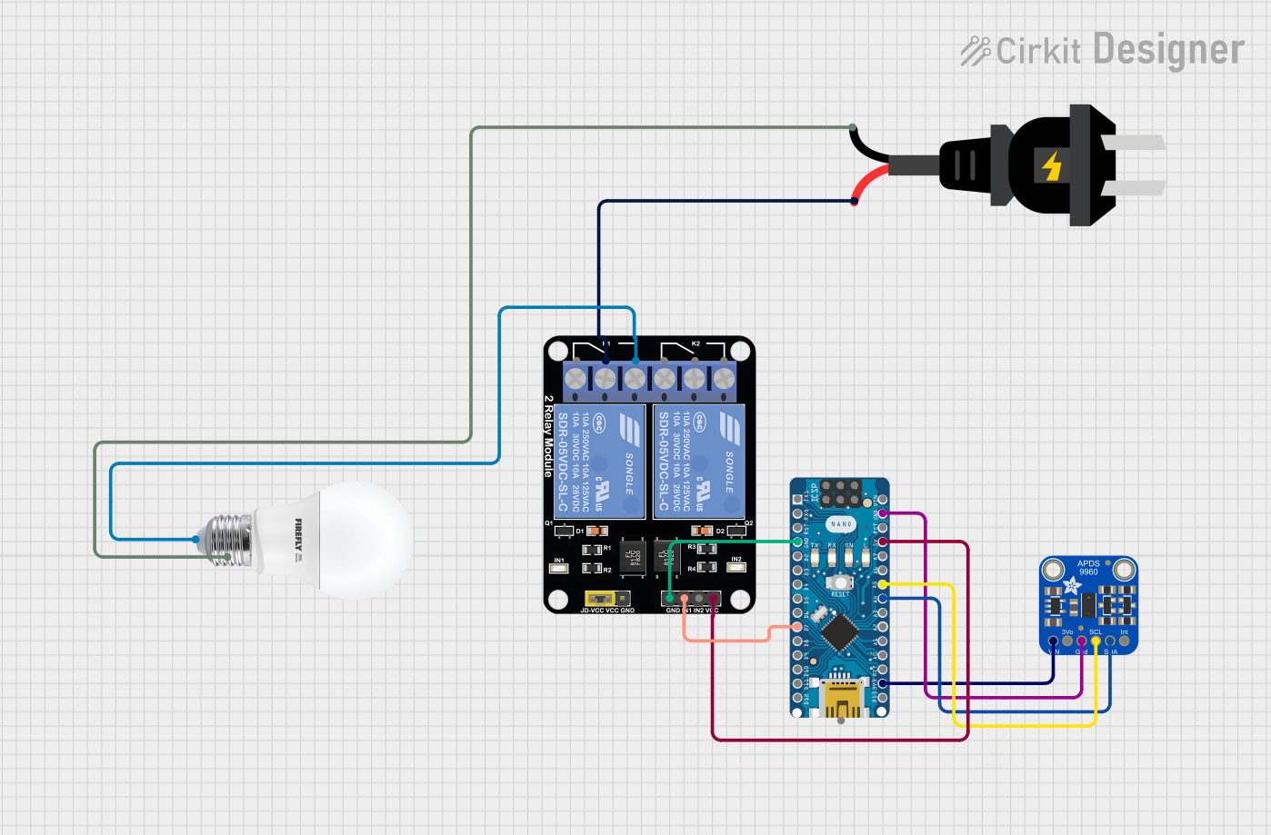
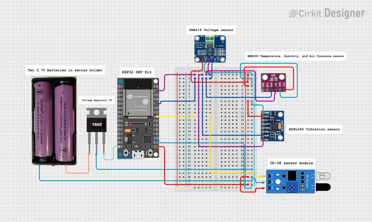

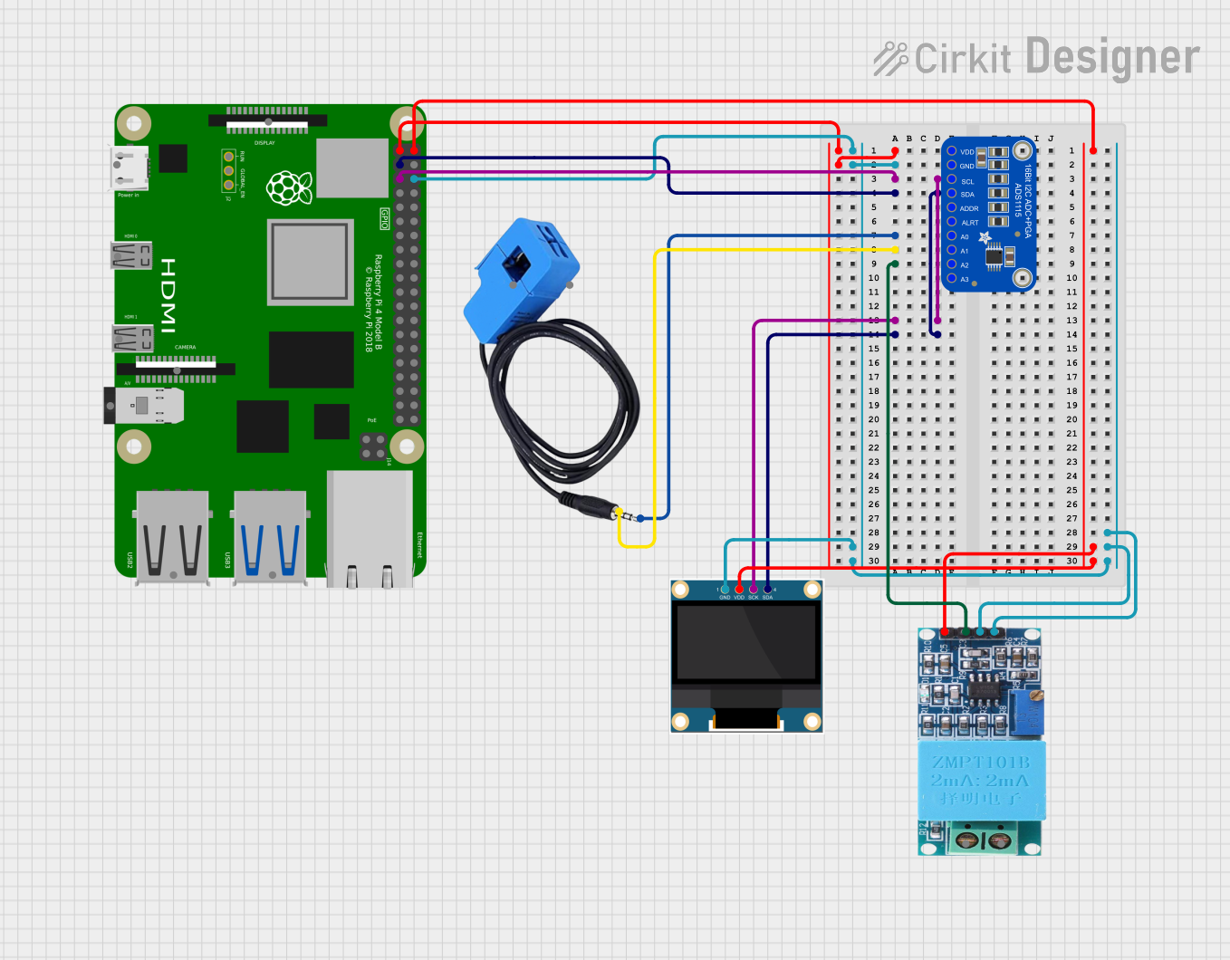
Explore Projects Built with Adafruit ADT7410
Technical Specifications
Key Technical Details
- Temperature Range: -55°C to +150°C
- Accuracy: ±0.5°C from -10°C to +85°C
- Resolution: Configurable, 16-bit (0.0078°C) default
- Interface: I2C (up to 400 kHz)
- Supply Voltage: 2.7V to 5.5V
- Operating Current: 210 μA (typical)
- Shutdown Current: 2 μA (typical)
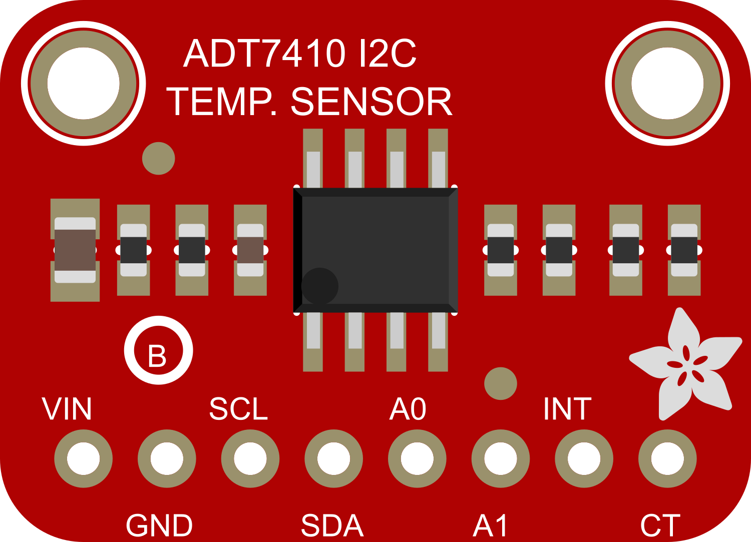
Pin Configuration and Descriptions
| Pin Number | Name | Description |
|---|---|---|
| 1 | GND | Ground connection for the sensor |
| 2 | SDA | I2C Data line |
| 3 | SCL | I2C Clock line |
| 4 | VDD | Supply voltage (2.7V to 5.5V) |
| 5 | A0 | I2C Address select pin |
| 6 | A1 | I2C Address select pin |
| 7 | CT | Critical temperature output (active low) |
| 8 | INT | Interrupt output (active low) |
Usage Instructions
Integration with a Circuit
- Power Supply: Connect the VDD pin to a 2.7V to 5.5V power supply and the GND pin to the ground.
- I2C Connection: Connect the SDA and SCL pins to the corresponding I2C data and clock lines on your microcontroller.
- Address Selection: The A0 and A1 pins can be connected to GND or VDD to set the I2C address of the sensor.
- Outputs: The CT and INT pins can be used for critical temperature alert and interrupt signals, respectively.
Important Considerations and Best Practices
- Ensure that the power supply is stable and within the specified voltage range.
- Use pull-up resistors on the I2C lines, typically 4.7kΩ to 10kΩ.
- Avoid placing the sensor near heat-generating components to prevent false readings.
- For accurate temperature readings, ensure good thermal contact between the sensor and the surface being monitored.
Example Code for Arduino UNO
#include <Wire.h>
#include <Adafruit_ADT7410.h>

Adafruit_ADT7410 tempSensor = Adafruit_ADT7410();

void setup() {
  Serial.begin(9600);
  // Initialize the ADT7410 sensor
  if (!tempSensor.begin()) {
    Serial.println("Failed to initialize ADT7410! Please check your connections.");
    while (1);
  }
  // Set to 16-bit resolution
  tempSensor.setResolution(ADT7410_RESOLUTION_16BIT);
}

void loop() {
  // Read and print out the temperature
  float temperature = tempSensor.readTempC();
  Serial.print("Temperature: ");
  Serial.print(temperature);
  Serial.println(" C");

  // Wait a second before reading again
  delay(1000);
}
Troubleshooting and FAQs
Common Issues
- Sensor Not Responding: Ensure that the I2C address is correctly set and that the sensor is properly powered.
- Inaccurate Readings: Check for sources of heat near the sensor and verify that the sensor has good thermal contact with the surface being monitored.
Solutions and Tips for Troubleshooting
- I2C Communication Failure: Use a logic analyzer or oscilloscope to check the SDA and SCL lines for proper communication signals.
- Check Connections: Verify that all connections are secure and that there are no broken wires or cold solder joints.
FAQs
Q: Can the ADT7410 be used with 3.3V systems? A: Yes, the ADT7410 can operate with supply voltages from 2.7V to 5.5V, making it suitable for both 3.3V and 5V systems.
Q: How can I change the I2C address of the sensor? A: The I2C address can be changed by connecting the A0 and A1 pins to either GND or VDD. The datasheet provides the address mapping based on these connections.
Q: What is the maximum I2C speed supported by the ADT7410? A: The ADT7410 supports I2C speeds up to 400 kHz.
Q: How do I use the CT and INT pins? A: The CT pin can be used to trigger an external interrupt when a critical temperature threshold is exceeded. The INT pin can be configured to signal when the temperature exceeds a user-defined limit. Both require additional setup in the sensor configuration.
This documentation provides a comprehensive guide to using the Adafruit ADT7410 temperature sensor. For further details and advanced configurations, refer to the official datasheet and application notes provided by Adafruit.