
How to Use VL6180X: Examples, Pinouts, and Specs
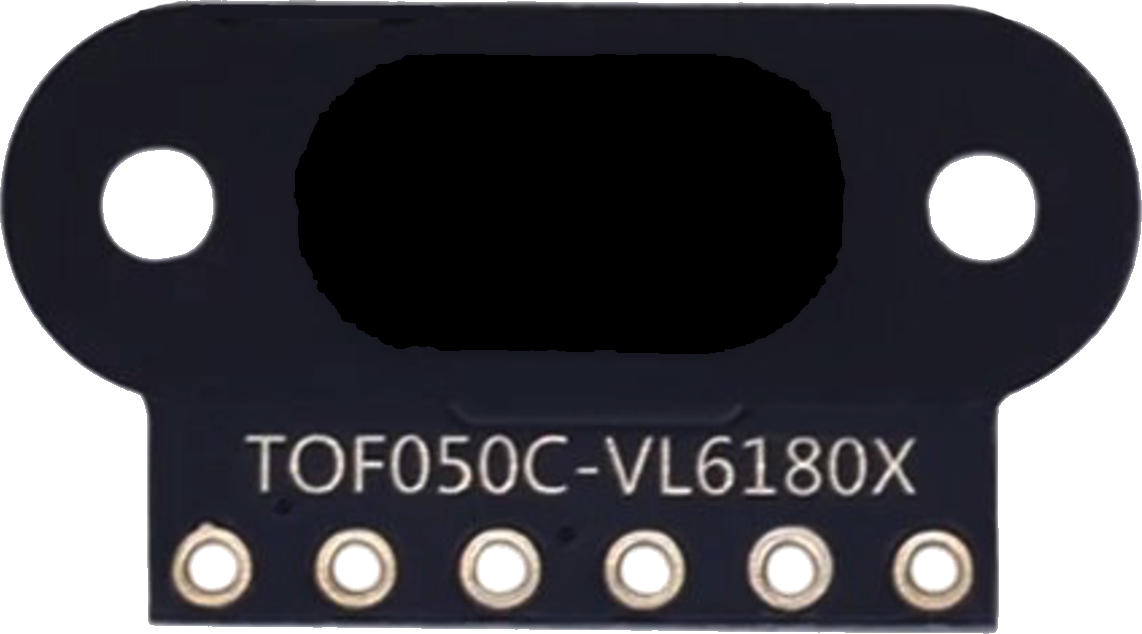
 Design with VL6180X in Cirkit Designer
Introduction
The VL6180X is a time-of-flight (ToF) distance sensor capable of measuring distances up to 100 mm with high accuracy. It integrates an infrared emitter and a photodetector, enabling it to measure proximity and ambient light levels. This compact sensor is widely used in robotics, automation, and consumer electronics for applications such as obstacle detection, gesture recognition, and ambient light sensing.
Explore Projects Built with VL6180X
 Open Project in Cirkit Designer
 Open Project in Cirkit Designer
 Open Project in Cirkit Designer
 Open Project in Cirkit Designer
Explore Projects Built with VL6180X
Open Project in Cirkit DesignerOpen Project in Cirkit DesignerOpen Project in Cirkit DesignerOpen Project in Cirkit DesignerCommon Applications
- Obstacle detection in robotics
- Gesture recognition in smart devices
- Proximity sensing in automation systems
- Ambient light level measurement for display brightness adjustment
Technical Specifications
The VL6180X is a highly integrated sensor with the following key specifications:
| Parameter | Value |
|---|---|
| Operating Voltage | 2.6 V to 3.3 V |
| Communication Interface | I²C |
| Distance Measurement Range | 0 mm to 100 mm |
| Ambient Light Sensing Range | 0.01 lux to 1000 lux |
| Current Consumption | 1.7 mA (typical during operation) |
| Infrared Wavelength | 850 nm |
| Operating Temperature Range | -20°C to +70°C |
| Package Dimensions | 4.8 mm × 2.8 mm × 1.0 mm |
Pin Configuration
The VL6180X has a simple pinout, as shown in the table below:
| Pin Name | Description |
|---|---|
| VDD | Power supply (2.6 V to 3.3 V) |
| GND | Ground |
| SDA | I²C data line |
| SCL | I²C clock line |
| GPIO0 | Interrupt output (optional, configurable) |
| GPIO1 | Additional interrupt or shutdown control (optional) |
Usage Instructions
Connecting the VL6180X to a Circuit
- Power Supply: Connect the VDD pin to a 3.3 V power source and the GND pin to ground.
- I²C Communication: Connect the SDA and SCL pins to the corresponding I²C pins on your microcontroller. Use pull-up resistors (typically 4.7 kΩ) on both SDA and SCL lines if not already present.
- Interrupts (Optional): If needed, connect GPIO0 or GPIO1 to your microcontroller for interrupt-based operation.
Important Considerations
- Ensure the sensor is not exposed to direct sunlight or reflective surfaces, as this may affect accuracy.
- Place the sensor at a fixed distance from the target for consistent measurements.
- Use proper decoupling capacitors (e.g., 0.1 µF) near the VDD pin to stabilize the power supply.
Example: Using VL6180X with Arduino UNO
Below is an example of how to use the VL6180X with an Arduino UNO to measure distance:
#include <Wire.h>
#include <Adafruit_VL6180X.h>

// Create an instance of the VL6180X sensor
Adafruit_VL6180X vl = Adafruit_VL6180X();

void setup() {
  Serial.begin(9600); // Initialize serial communication at 9600 baud
  Wire.begin();       // Initialize I²C communication

  // Initialize the VL6180X sensor
  if (!vl.begin()) {
    Serial.println("Failed to find VL6180X sensor! Check connections.");
    while (1); // Halt execution if sensor initialization fails
  }
  Serial.println("VL6180X sensor initialized successfully.");
}

void loop() {
  // Read the distance in millimeters
  uint8_t distance = vl.readRange();

  // Check for errors in the measurement
  if (vl.readRangeStatus() != VL6180X_ERROR_NONE) {
    Serial.println("Error reading range!");
  } else {
    Serial.print("Distance: ");
    Serial.print(distance);
    Serial.println(" mm");
  }

  delay(500); // Wait for 500 ms before the next reading
}
Best Practices
- Use a stable power supply to avoid measurement fluctuations.
- Keep the sensor clean and free from dust or debris.
- Avoid placing the sensor too close to highly reflective surfaces.
Troubleshooting and FAQs
Common Issues
Sensor Not Detected on I²C Bus
- Solution: Verify the wiring, especially the SDA and SCL connections. Ensure pull-up resistors are present on the I²C lines.
- Tip: Use an I²C scanner sketch to confirm the sensor's address.
Inaccurate Distance Measurements
- Solution: Ensure the sensor is not exposed to direct sunlight or reflective surfaces. Check for obstructions near the sensor.
- Tip: Calibrate the sensor if necessary using the manufacturer's guidelines.
Intermittent Readings
- Solution: Check the power supply for stability. Add decoupling capacitors near the sensor.
- Tip: Ensure the I²C clock speed is within the sensor's supported range (typically 100 kHz or 400 kHz).
FAQs
Q: What is the default I²C address of the VL6180X?
A: The default I²C address is 0x29. It can be changed in software if needed.
Q: Can the VL6180X measure distances beyond 100 mm?
A: No, the VL6180X is designed for accurate measurements up to 100 mm. For longer ranges, consider other sensors like the VL53L0X.
Q: Is the VL6180X suitable for outdoor use?
A: The sensor can be used outdoors, but its performance may degrade in direct sunlight or extreme environmental conditions.
Q: How do I handle multiple VL6180X sensors on the same I²C bus?
A: Use the GPIO1 pin to reset individual sensors and assign unique I²C addresses during initialization.
By following this documentation, you can effectively integrate the VL6180X into your projects and troubleshoot common issues.