How to Use Ceramic Resonator (2-pin): Examples, Pinouts, and Specs
Introduction
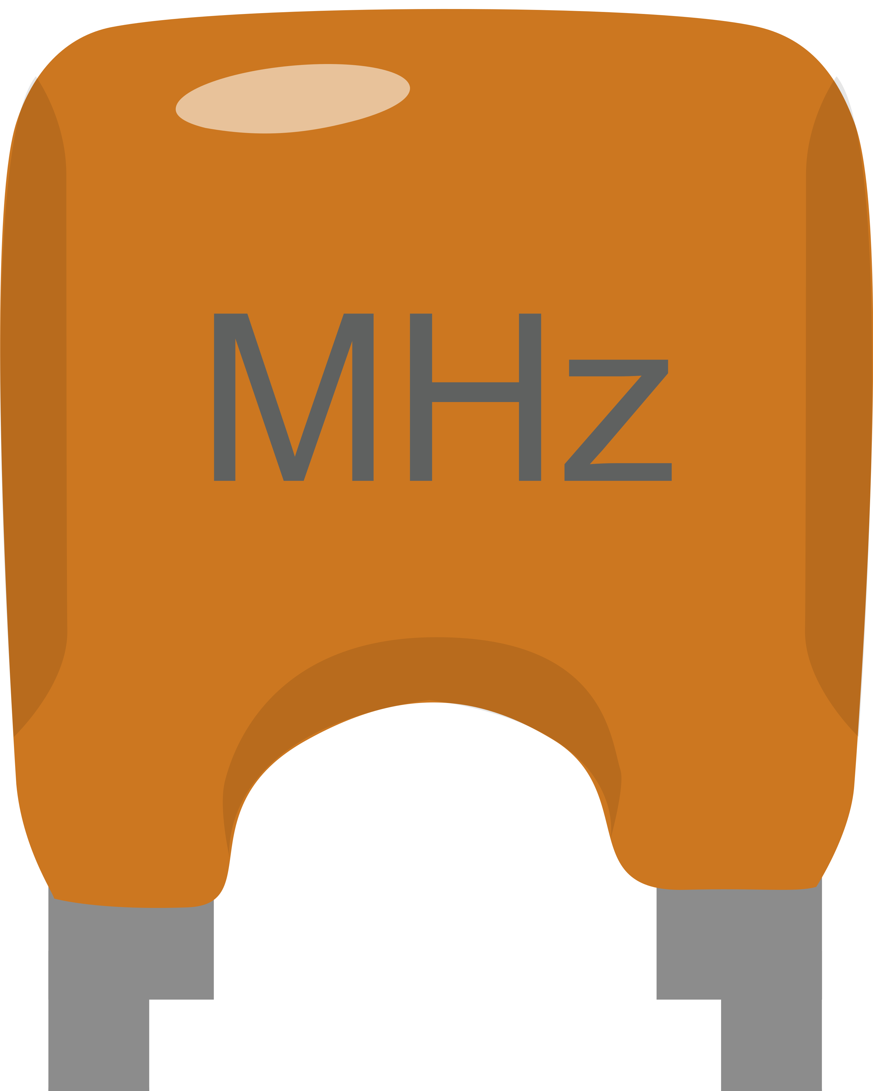
A Ceramic Resonator (2-pin) is a compact, cost-effective passive component designed to provide stable frequency oscillations in electronic circuits. Unlike quartz crystals, ceramic resonators offer a balance between performance and cost, making them a popular choice in consumer electronics. They are frequently used in microcontroller applications, clock generation for digital ICs, and timing circuits where precise frequency control is not critically stringent.
Explore Projects Built with Ceramic Resonator (2-pin)
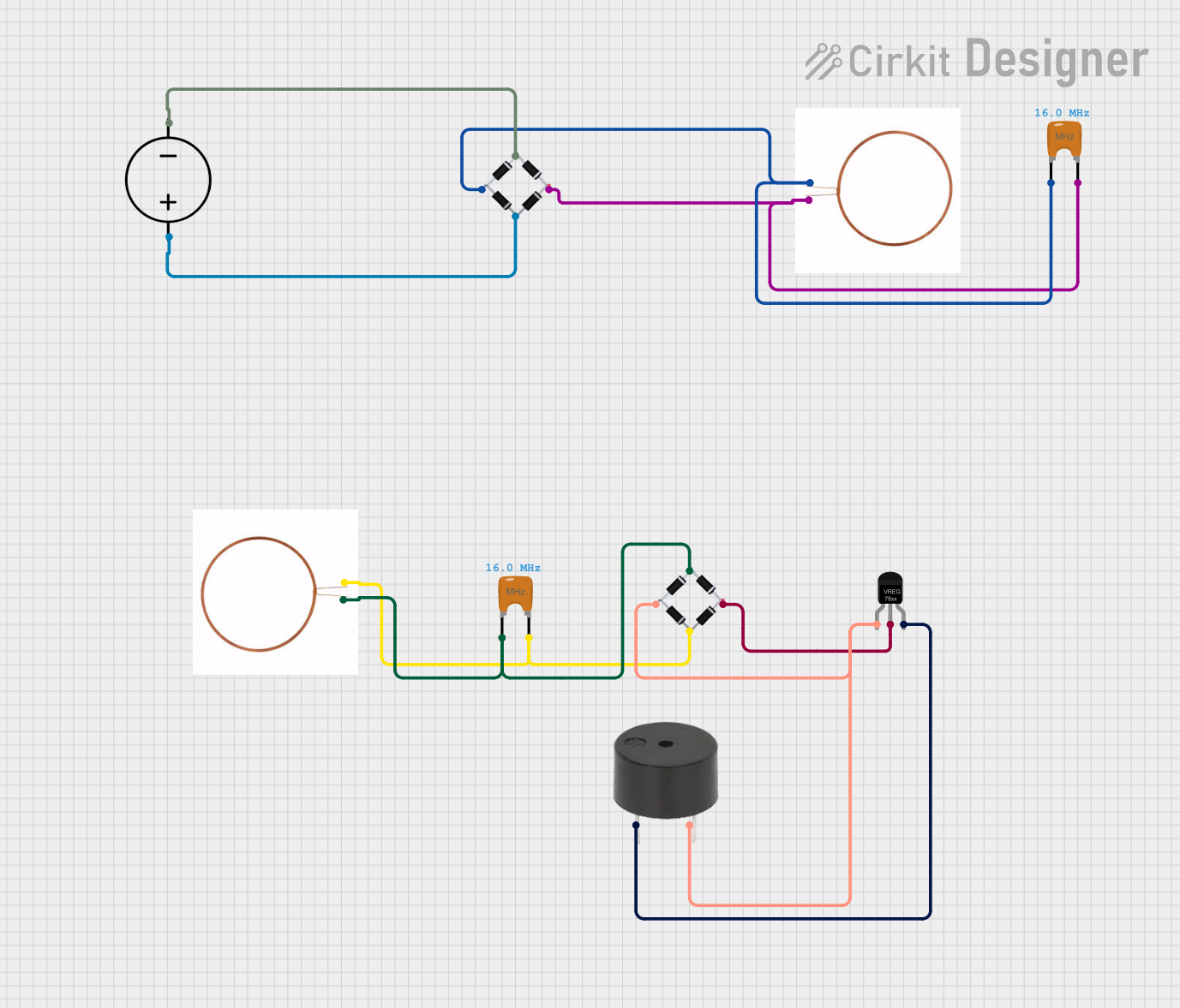
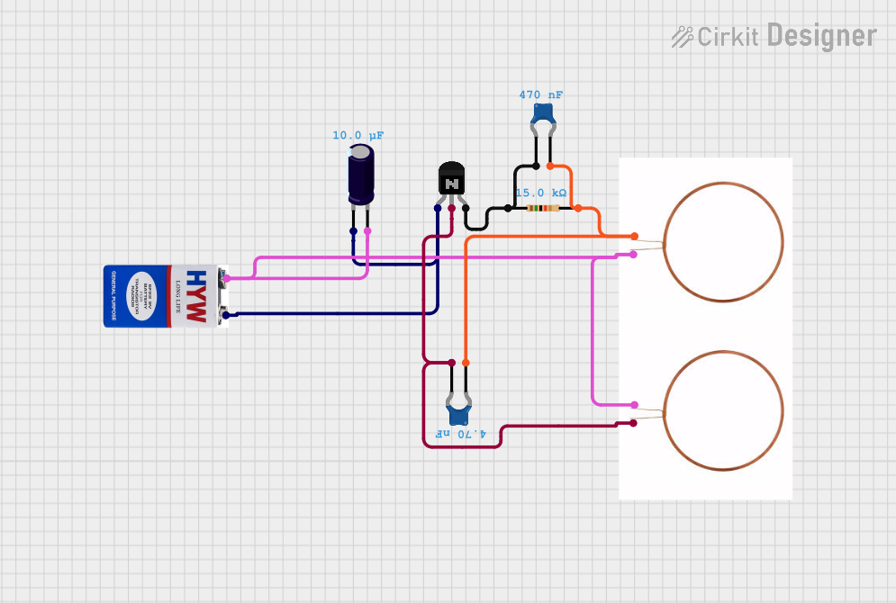
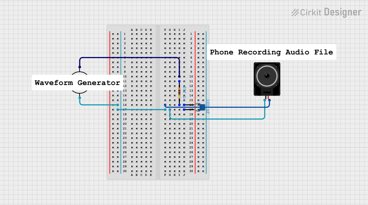

Explore Projects Built with Ceramic Resonator (2-pin)
Technical Specifications
General Characteristics
- Frequency Range: Typically from 190 kHz to 8 MHz
- Frequency Tolerance: ±0.5% to ±0.3%
- Operating Temperature: -20°C to +80°C
- Aging: Approximately ±0.3% change per year
Electrical Characteristics
| Parameter | Symbol | Condition | Min | Typ | Max | Unit |
|---|---|---|---|---|---|---|
| Resonant Frequency | f0 | MHz | ||||
| Oscillation Capacitance | Co | pF | ||||
| Resonant Impedance | Zo | 30 | 100 | Ω | ||
| Load Capacitance | CL | 15 | pF |
Pin Configuration and Descriptions
| Pin Number | Name | Description |
|---|---|---|
| 1 | OUT | Oscillation output, connects to the circuit |
| 2 | GND | Ground, provides a reference point for zero voltage |
Usage Instructions
Integration into a Circuit
To use a Ceramic Resonator (2-pin) in a circuit:
- Connect the first pin (OUT) to the input of the oscillator circuit or the clock input of a microcontroller.
- Connect the second pin (GND) to the common ground of the circuit.
Best Practices
- Ensure that the resonator is placed close to the microcontroller or IC to minimize trace lengths and potential interference.
- A small capacitor (typically 22pF) may be placed between each pin of the resonator and ground to stabilize the oscillation, although this is not always necessary.
- Avoid placing the resonator near high-heat components to prevent frequency drift due to temperature changes.
Troubleshooting and FAQs
Common Issues
- No Oscillation: Ensure the resonator is properly soldered and the pins are not shorted.
- Frequency Drift: Check for temperature variations or nearby heat sources that could affect the resonator.
FAQs
Q: Can I replace a crystal oscillator with a ceramic resonator? A: Yes, in many cases, a ceramic resonator can replace a crystal oscillator, especially when the application does not require high precision.
Q: Do I need external capacitors with a ceramic resonator? A: It depends on the specific resonator and application. Some resonators are designed to work without external capacitors, but others may require them for stability.
Q: What is the typical lifespan of a ceramic resonator? A: Ceramic resonators are generally very reliable and can last many years, but the frequency can drift slightly over time due to aging.
Example Code for Arduino UNO
Below is an example of how to set up an Arduino UNO to use an external Ceramic Resonator (2-pin) for its clock source. Note that this requires changing the fuses on the microcontroller, which is an advanced topic and should be done with caution.
// This code assumes that the Arduino is using the ceramic resonator as its clock source.
// No specific code is required to use the resonator itself, as it is a hardware setup.

void setup() {
  // Initialize digital pin LED_BUILTIN as an output.
  pinMode(LED_BUILTIN, OUTPUT);
}

void loop() {
  // Turn the LED on (HIGH is the voltage level)
  digitalWrite(LED_BUILTIN, HIGH);
  // Wait for a second
  delay(1000);
  // Turn the LED off by making the voltage LOW
  digitalWrite(LED_BUILTIN, LOW);
   // Wait for a second
  delay(1000);
}

// Note: The delay function relies on the microcontroller's clock source to function properly.
// If the resonator is not functioning as expected, the timing of the delay will be incorrect.
Remember that the actual implementation of a ceramic resonator as a clock source for a microcontroller like the Arduino UNO requires hardware configuration and may involve burning the bootloader with the new fuse settings that match the resonator's frequency. This is beyond the scope of this document and should only be attempted by experienced users.