How to Use RFID RC522 I2C 4pin: Examples, Pinouts, and Specs
Introduction
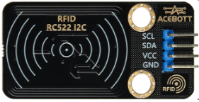
The RFID RC522 is a compact and cost-effective RFID reader/writer module that communicates via the I2C interface. Operating at a frequency of 13.56 MHz, it is capable of reading and writing to RFID tags. This module is widely used in applications such as access control, inventory management, and automation systems. Its small size, low power consumption, and ease of integration make it a popular choice for both hobbyists and professionals.
Explore Projects Built with RFID RC522 I2C 4pin


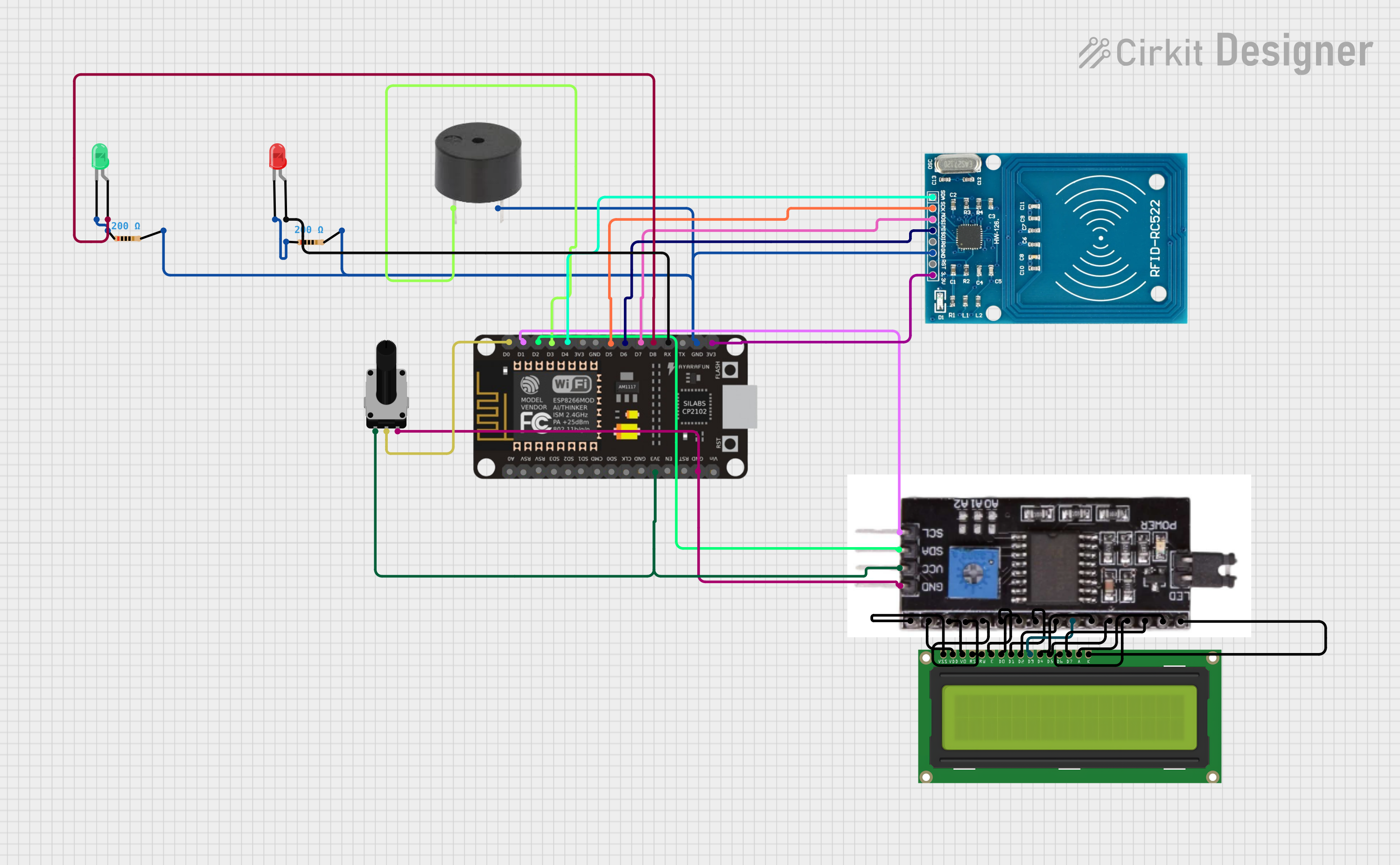
Explore Projects Built with RFID RC522 I2C 4pin
Common Applications
- Access control systems (e.g., door locks, attendance systems)
- Inventory and asset tracking
- Contactless payment systems
- Smart automation projects
- Arduino-based RFID projects
Technical Specifications
The RFID RC522 module is designed for efficient and reliable RFID communication. Below are its key technical details:
| Parameter | Specification |
|---|---|
| Operating Voltage | 3.3V |
| Communication Interface | I2C (4-pin configuration) |
| Operating Frequency | 13.56 MHz |
| Maximum Data Rate | 10 Mbps |
| Current Consumption | 13-26 mA (active mode) |
| Supported RFID Tags | ISO/IEC 14443 Type A cards |
| Operating Temperature | -20°C to 80°C |
| Dimensions | 40mm x 60mm |
Pin Configuration
The RFID RC522 I2C module uses a 4-pin interface for communication. Below is the pinout description:
| Pin | Name | Description |
|---|---|---|
| 1 | VCC | Power supply input (3.3V) |
| 2 | GND | Ground connection |
| 3 | SDA | I2C data line (connect to Arduino SDA pin) |
| 4 | SCL | I2C clock line (connect to Arduino SCL pin) |
Usage Instructions
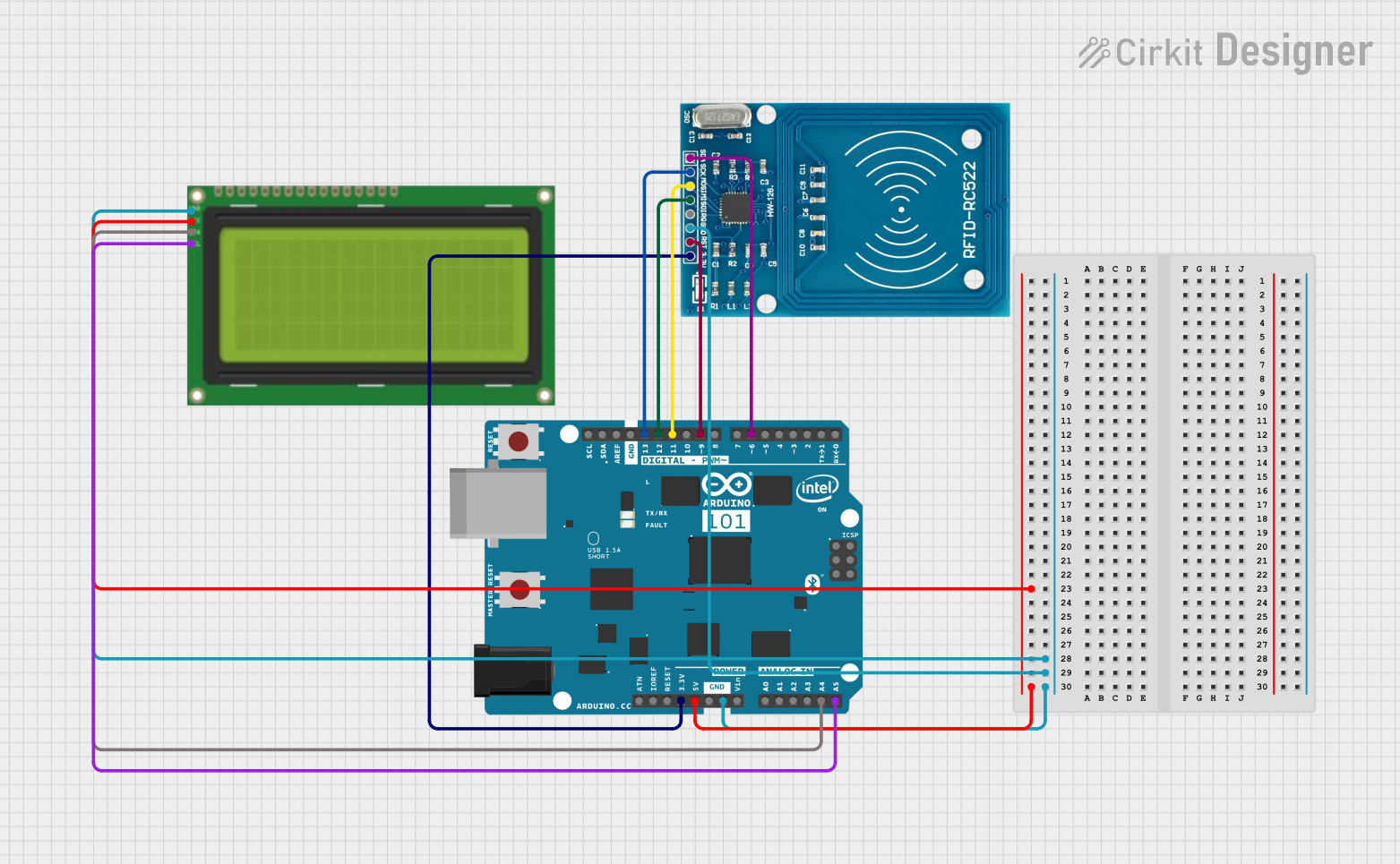
Connecting the RFID RC522 to an Arduino UNO
To use the RFID RC522 module with an Arduino UNO, follow these steps:
- Wiring: Connect the module to the Arduino as per the table below:
- VCC → 3.3V
- GND → GND
- SDA → A4 (Arduino SDA pin)
- SCL → A5 (Arduino SCL pin)
- Install Required Libraries: Download and install the
MFRC522library from the Arduino Library Manager. - Upload Code: Use the example code below to test the module.
Example Code
The following Arduino sketch demonstrates how to initialize the RFID RC522 module and read an RFID tag's UID:
#include <Wire.h>
#include <MFRC522.h> // Include the MFRC522 library

#define RST_PIN 9  // Reset pin for the RC522 module
#define SDA_PIN 10 // SDA pin for the RC522 module

MFRC522 rfid(SDA_PIN, RST_PIN); // Create an instance of the MFRC522 class

void setup() {
  Serial.begin(9600); // Initialize serial communication
  Wire.begin();       // Initialize I2C communication
  rfid.PCD_Init();    // Initialize the RC522 module
  Serial.println("Place an RFID tag near the reader...");
}

void loop() {
  // Check if an RFID tag is present
  if (!rfid.PICC_IsNewCardPresent() || !rfid.PICC_ReadCardSerial()) {
    return; // Exit if no tag is detected
  }

  // Print the UID of the detected tag
  Serial.print("Tag UID: ");
  for (byte i = 0; i < rfid.uid.size; i++) {
    Serial.print(rfid.uid.uidByte[i], HEX); // Print each byte in hexadecimal
    Serial.print(" ");
  }
  Serial.println();

  rfid.PICC_HaltA(); // Halt communication with the tag
}
Important Considerations
- Power Supply: Ensure the module is powered with 3.3V. Supplying 5V may damage the module.
- Pull-up Resistors: If the I2C lines (SDA and SCL) are not functioning correctly, add 4.7kΩ pull-up resistors.
- Tag Compatibility: Use RFID tags that comply with the ISO/IEC 14443 Type A standard.
Troubleshooting and FAQs
Common Issues and Solutions
Module Not Detected:
- Verify the wiring connections between the module and the Arduino.
- Ensure the module is powered with 3.3V, not 5V.
- Check if the I2C address of the module matches the library's default settings.
Unable to Read Tags:
- Ensure the RFID tag is compatible with the RC522 module (ISO/IEC 14443 Type A).
- Place the tag closer to the module's antenna for better detection.
Intermittent Communication:
- Check for loose connections or faulty jumper wires.
- Add pull-up resistors to the SDA and SCL lines if necessary.
FAQs
Q: Can I use the RFID RC522 module with a 5V microcontroller?
A: Yes, but you must use a logic level shifter to step down the 5V signals to 3.3V for the module.
Q: What is the maximum range of the RFID RC522 module?
A: The module typically has a range of 2-5 cm, depending on the tag and environmental conditions.
Q: Can the module write data to RFID tags?
A: Yes, the RC522 module supports both reading and writing to compatible RFID tags.
By following this documentation, you can effectively integrate the RFID RC522 I2C module into your projects.