How to Use QTR-MD-05RC: Examples, Pinouts, and Specs
Introduction
The QTR-MD-05RC, manufactured by Pololu, is an infrared (IR) reflective sensor array designed for line-following and object detection applications in robotics. This compact and versatile module features five IR emitter and phototransistor pairs, enabling it to detect the presence of nearby objects or track lines on a surface by measuring the reflection of infrared light. The QTR-MD-05RC is ideal for use in autonomous robots, industrial automation, and educational projects.
Explore Projects Built with QTR-MD-05RC


Explore Projects Built with QTR-MD-05RC
Common Applications
- Line-following robots
- Edge detection for robotic navigation
- Object detection and proximity sensing
- Industrial automation systems
- Educational robotics projects
Technical Specifications
The QTR-MD-05RC sensor array is designed for ease of use and compatibility with a wide range of microcontrollers. Below are its key technical details:
Key Technical Details
| Parameter | Value |
|---|---|
| Operating Voltage | 2.9 V to 5.5 V |
| Average Current Consumption | 7 mA (typical) |
| Output Type | Digital pulse width (RC time measurement) |
| IR Wavelength | 940 nm |
| Detection Range | 3 mm to 30 mm (depending on surface) |
| Dimensions | 33 mm × 8 mm × 3 mm |
| Weight | 0.6 g |
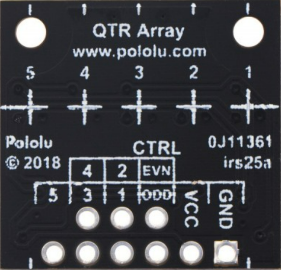
Pin Configuration and Descriptions
The QTR-MD-05RC has an 8-pin interface. The table below describes each pin:
| Pin Number | Name | Description |
|---|---|---|
| 1 | VCC | Power supply input (2.9 V to 5.5 V). |
| 2 | GND | Ground connection. |
| 3 | OUT1 | Digital output for sensor 1 (leftmost sensor). |
| 4 | OUT2 | Digital output for sensor 2. |
| 5 | OUT3 | Digital output for sensor 3 (center sensor). |
| 6 | OUT4 | Digital output for sensor 4. |
| 7 | OUT5 | Digital output for sensor 5 (rightmost sensor). |
| 8 | CTRL | Control pin for enabling/disabling the IR emitters (active low). |
Usage Instructions
The QTR-MD-05RC is straightforward to use in a circuit. It outputs digital signals that correspond to the reflectivity of the surface beneath each sensor. Follow the steps below to integrate the sensor array into your project:
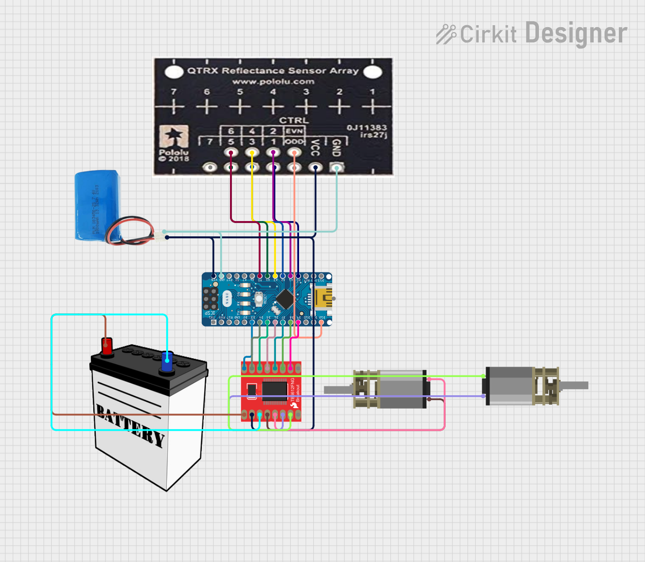
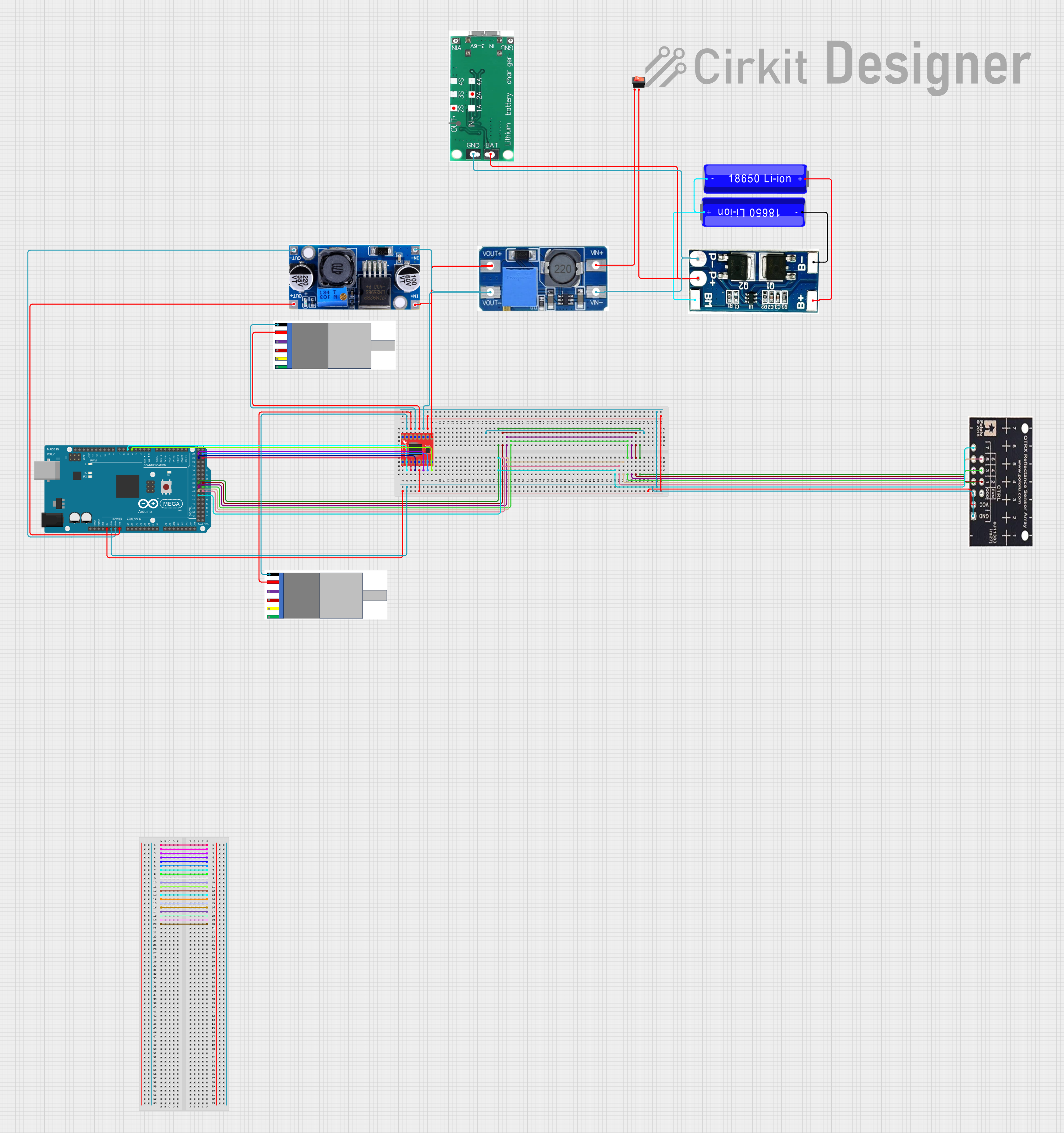
Connecting the QTR-MD-05RC
- Power the Module: Connect the
VCCpin to a 3.3 V or 5 V power source and theGNDpin to ground. - Connect Outputs: Connect the
OUT1toOUT5pins to the digital input pins of your microcontroller. - Control Pin: Optionally, connect the
CTRLpin to a digital output pin of your microcontroller to enable or disable the IR emitters. Leave it unconnected if you want the emitters to remain enabled.
Reading Sensor Outputs
The QTR-MD-05RC outputs a digital pulse whose width corresponds to the reflectivity of the surface. A shorter pulse indicates a more reflective surface (e.g., white), while a longer pulse indicates a less reflective surface (e.g., black).
Example: Using with Arduino UNO
Below is an example Arduino sketch to read the sensor outputs and print the results to the Serial Monitor:
// QTR-MD-05RC Example Code for Arduino UNO
// This code reads the pulse width from each sensor and prints the values
// to the Serial Monitor. Ensure the QTR-MD-05RC is properly connected.

#define NUM_SENSORS 5  // Number of sensors on the QTR-MD-05RC
const int sensorPins[NUM_SENSORS] = {2, 3, 4, 5, 6}; // Digital pins for OUT1-OUT5

void setup() {
  Serial.begin(9600); // Initialize Serial communication
  for (int i = 0; i < NUM_SENSORS; i++) {
    pinMode(sensorPins[i], INPUT); // Set sensor pins as inputs
  }
}

void loop() {
  for (int i = 0; i < NUM_SENSORS; i++) {
    pinMode(sensorPins[i], OUTPUT); // Set pin to output mode
    digitalWrite(sensorPins[i], LOW); // Discharge capacitor
    delayMicroseconds(10); // Wait for capacitor to discharge
    pinMode(sensorPins[i], INPUT); // Set pin back to input mode

    // Measure the time it takes for the pin to go HIGH
    unsigned long duration = pulseIn(sensorPins[i], HIGH, 3000);

    // Print the duration for each sensor
    Serial.print("Sensor ");
    Serial.print(i + 1);
    Serial.print(": ");
    Serial.print(duration);
    Serial.print(" us\t");
  }
  Serial.println(); // Print a new line after all sensor readings
  delay(100); // Small delay before the next reading
}
Important Considerations
- Surface Reflectivity: The sensor's performance depends on the reflectivity of the surface. For best results, use high-contrast lines (e.g., black lines on a white background).
- Emitter Control: Use the
CTRLpin to disable the IR emitters when not in use to save power. - Ambient Light: Minimize ambient IR light interference by shielding the sensor or using it in controlled lighting conditions.
Troubleshooting and FAQs
Common Issues and Solutions
No Output from Sensors
- Ensure the
VCCandGNDpins are properly connected. - Verify that the
CTRLpin is not being held low (disabling the emitters).
- Ensure the
Inconsistent Readings
- Check for ambient IR light interference and reduce it if possible.
- Ensure the sensor array is positioned at the correct height (3 mm to 30 mm) above the surface.
Sensors Not Detecting Lines
- Verify that the line has sufficient contrast with the background.
- Clean the sensor array to remove dust or debris.
FAQs
Q: Can the QTR-MD-05RC be used with a 3.3 V microcontroller?
A: Yes, the QTR-MD-05RC operates within a voltage range of 2.9 V to 5.5 V, making it compatible with 3.3 V systems.
Q: How do I adjust the sensitivity of the sensors?
A: The sensitivity is determined by the reflectivity of the surface and the height of the sensor array. Adjust the height for optimal performance.
Q: Can I use fewer than five sensors?
A: Yes, you can use only the outputs you need and leave the unused outputs unconnected.
Q: What is the purpose of the CTRL pin?
A: The CTRL pin allows you to enable or disable the IR emitters. This is useful for saving power or reducing interference when the sensor is not in use.