How to Use ESP8266: Examples, Pinouts, and Specs
Introduction
The ESP8266 is a low-cost Wi-Fi microchip with a full TCP/IP stack and microcontroller capability. It is widely used in Internet of Things (IoT) applications due to its affordability, ease of use, and robust feature set. The ESP8266 can operate as both a standalone microcontroller or as a Wi-Fi module for other microcontrollers, making it highly versatile.
Explore Projects Built with ESP8266
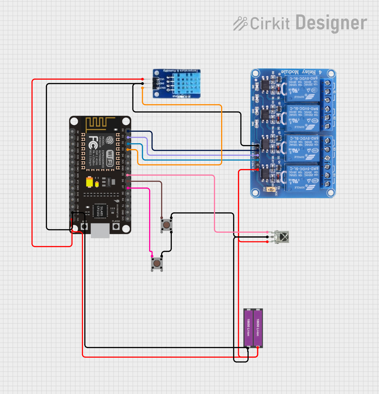

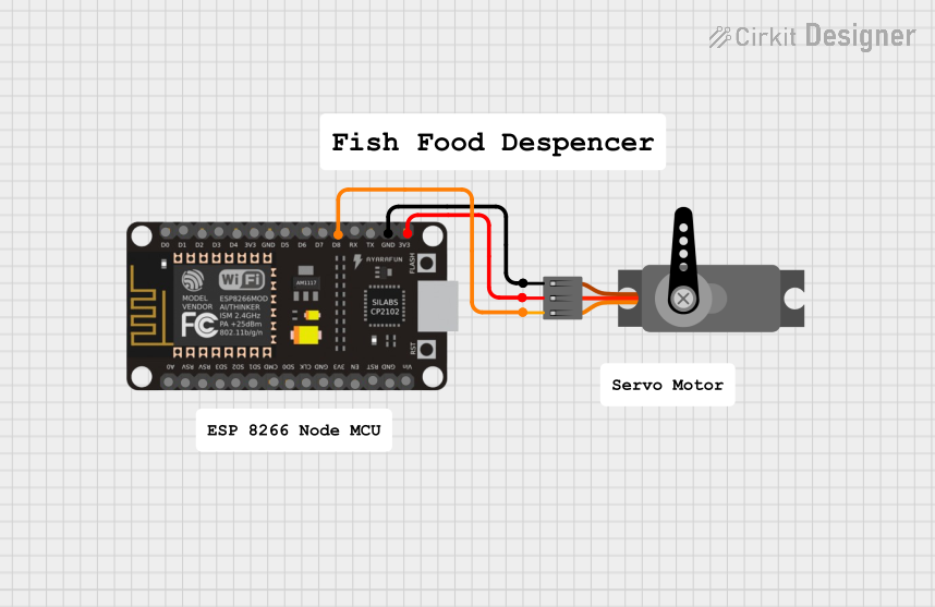

Explore Projects Built with ESP8266
Common Applications and Use Cases
- Home automation systems
- Smart appliances
- Wireless sensor networks
- IoT prototyping and development
- Remote data logging and monitoring
- Wi-Fi-enabled robotics
Technical Specifications
The ESP8266 is available in various module formats, with the ESP-01 being one of the most popular. Below are the key technical details:
Key Technical Details
- Operating Voltage: 3.0V to 3.6V (3.3V recommended)
- Current Consumption:
- Idle: ~10mA
- Active (Wi-Fi TX): ~170mA
- Processor: 32-bit Tensilica L106 running at 80MHz (can be overclocked to 160MHz)
- Flash Memory: 512KB to 4MB (varies by module)
- Wi-Fi Standards: 802.11 b/g/n
- GPIO Pins: Up to 17 (varies by module)
- Communication Protocols: UART, SPI, I2C, PWM, ADC
- Operating Temperature: -40°C to 125°C
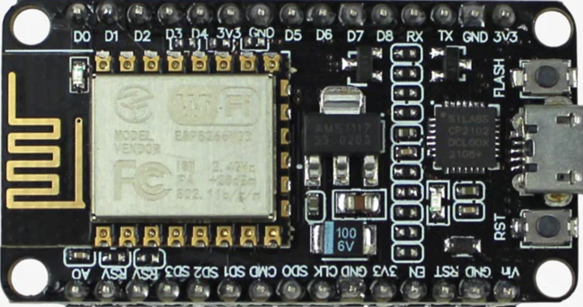
Pin Configuration and Descriptions
Below is the pinout for the ESP-01 module, one of the most commonly used ESP8266 variants:
| Pin | Name | Description |
|---|---|---|
| 1 | VCC | Power input (3.3V). Do not exceed 3.6V. |
| 2 | GND | Ground connection. |
| 3 | TX | UART Transmit pin. Used for serial communication. |
| 4 | RX | UART Receive pin. Used for serial communication. |
| 5 | CH_PD/EN | Chip enable. Must be pulled high (3.3V) to enable the module. |
| 6 | GPIO0 | General-purpose I/O pin. Used for boot mode selection during startup. |
| 7 | GPIO2 | General-purpose I/O pin. |
| 8 | RST | Reset pin. Pull low to reset the module. |
Usage Instructions
The ESP8266 can be used as a standalone microcontroller or as a Wi-Fi module for other microcontrollers like the Arduino UNO. Below are the steps to get started:
Using the ESP8266 with an Arduino UNO
Wiring the ESP8266 to the Arduino UNO:
- Connect the ESP8266's
VCCandCH_PDpins to a 3.3V power source. - Connect
GNDto the Arduino's ground. - Connect the
TXpin of the ESP8266 to a voltage divider (to step down the Arduino's 5V TX signal to 3.3V) and then to the Arduino'sTXpin. - Connect the
RXpin of the ESP8266 to the Arduino'sRXpin.
- Connect the ESP8266's
Install the ESP8266 Board Package:
- Open the Arduino IDE.
- Go to
File > Preferencesand add the following URL to the "Additional Board Manager URLs" field:http://arduino.esp8266.com/stable/package_esp8266com_index.json - Go to
Tools > Board > Boards Manager, search for "ESP8266," and install the package.
Upload Code to the ESP8266: Below is an example code to connect the ESP8266 to a Wi-Fi network and print the IP address:
#include <ESP8266WiFi.h> // Include the ESP8266 Wi-Fi library

const char* ssid = "Your_SSID";       // Replace with your Wi-Fi network name
const char* password = "Your_Password"; // Replace with your Wi-Fi password

void setup() {
  Serial.begin(115200); // Start serial communication at 115200 baud
  WiFi.begin(ssid, password); // Connect to the Wi-Fi network

  Serial.print("Connecting to Wi-Fi");
  while (WiFi.status() != WL_CONNECTED) {
    delay(1000); // Wait for 1 second
    Serial.print(".");
  }
  Serial.println("\nConnected to Wi-Fi!");
  Serial.print("IP Address: ");
  Serial.println(WiFi.localIP()); // Print the module's IP address
}

void loop() {
  // Add your main code here
}
Important Considerations and Best Practices
- Power Supply: The ESP8266 requires a stable 3.3V power supply. Using a 5V supply can damage the module.
- Voltage Level Shifting: The ESP8266's GPIO pins are not 5V tolerant. Use a voltage divider or level shifter when interfacing with 5V logic.
- Antenna Placement: Ensure the module's antenna is not obstructed by metal objects to maintain good Wi-Fi signal strength.
- Boot Modes: The GPIO0 pin determines the boot mode:
- Pull GPIO0 low during power-up to enter flash mode (for uploading firmware).
- Pull GPIO0 high during power-up for normal operation.
Troubleshooting and FAQs
Common Issues
ESP8266 Not Responding to AT Commands:
- Solution: Ensure the baud rate in your serial monitor matches the ESP8266's default baud rate (usually 115200 or 9600).
- Tip: Check the wiring and ensure the
CH_PDpin is pulled high.
Wi-Fi Connection Fails:
- Solution: Double-check the SSID and password in your code.
- Tip: Ensure the Wi-Fi network is within range and not using unsupported security protocols.
Module Overheating:
- Solution: Verify that the power supply is providing a stable 3.3V and sufficient current (at least 300mA).
- Tip: Avoid powering the ESP8266 directly from the Arduino's 3.3V pin, as it may not provide enough current.
Frequent Resets or Instability:
- Solution: Add a 10µF capacitor between
VCCandGNDto stabilize the power supply. - Tip: Check for loose connections or poor soldering.
- Solution: Add a 10µF capacitor between
FAQs
Q: Can the ESP8266 be programmed using the Arduino IDE?
A: Yes, the ESP8266 can be programmed directly using the Arduino IDE by installing the ESP8266 board package.Q: What is the maximum range of the ESP8266?
A: The range depends on the environment but is typically around 50 meters indoors and 100 meters outdoors.Q: Can the ESP8266 handle HTTPS requests?
A: Yes, the ESP8266 supports HTTPS, but it requires additional memory and may need optimized libraries for large-scale applications.Q: Is the ESP8266 compatible with 5V logic?
A: No, the ESP8266 operates at 3.3V logic levels. Use a level shifter or voltage divider for 5V systems.