How to Use Gy271 Magnometer: Examples, Pinouts, and Specs
Introduction
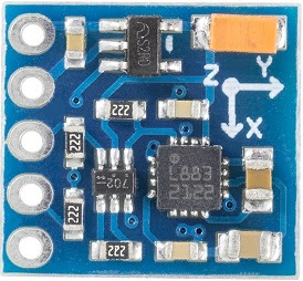
The GY-271 Magnetometer is a digital compass sensor designed to measure the Earth's magnetic field in three dimensions (X, Y, and Z axes). It is based on the HMC5883L or QMC5883L chip, depending on the module version. This sensor is widely used in navigation systems, robotics, drones, and mobile devices to determine orientation and heading. Its compact size, low power consumption, and high sensitivity make it an excellent choice for applications requiring precise directional data.
Common applications include:
- Navigation systems for determining heading and orientation
- Robotics for pathfinding and obstacle avoidance
- Drones for stabilization and direction control
- Mobile devices for augmented reality and compass functionality
Explore Projects Built with Gy271 Magnometer

Explore Projects Built with Gy271 Magnometer
Technical Specifications
- Chipset: HMC5883L or QMC5883L (depending on the module version)
- Operating Voltage: 3.3V to 5V
- Communication Protocol: I2C
- Measurement Range: ±1.3 to ±8 Gauss
- Resolution: 13-bit ADC
- Operating Temperature: -40°C to +85°C
- Dimensions: 15mm x 13mm x 3mm (approx.)
- Power Consumption: <100 µA in active mode
Pin Configuration and Descriptions
The GY-271 module typically has 4 pins for interfacing:
| Pin | Name | Description |
|---|---|---|
| 1 | VCC | Power supply (3.3V to 5V) |
| 2 | GND | Ground |
| 3 | SDA | I2C data line |
| 4 | SCL | I2C clock line |
Usage Instructions
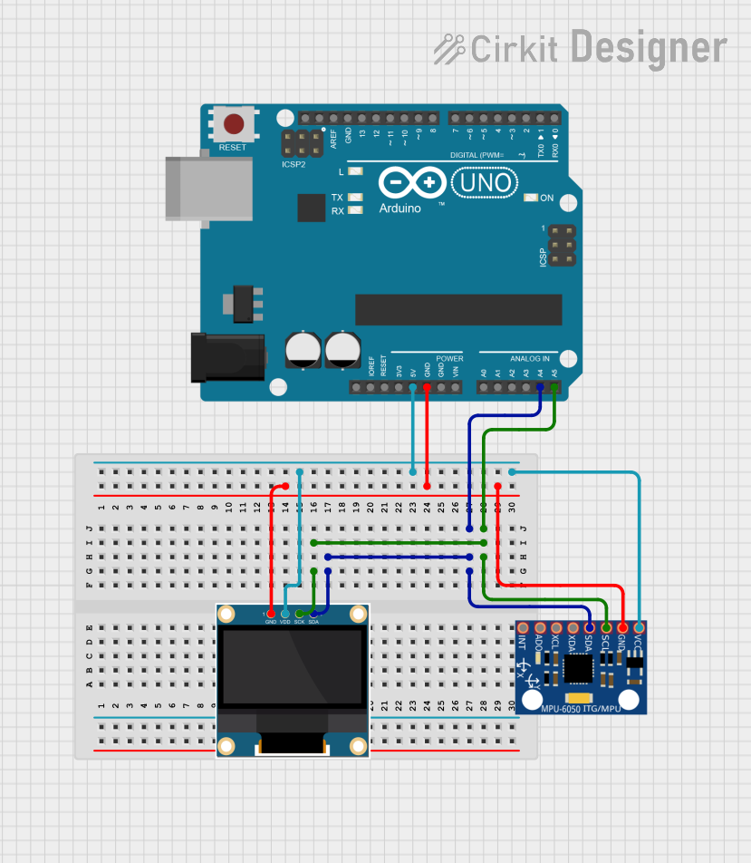
Connecting the GY-271 to an Arduino UNO
To use the GY-271 Magnetometer with an Arduino UNO, follow these steps:
- Wiring: Connect the module to the Arduino as follows:
- VCC to Arduino 5V
- GND to Arduino GND
- SDA to Arduino A4 (I2C data line)
- SCL to Arduino A5 (I2C clock line)
- Install Required Libraries: Install the
Adafruit_SensorandAdafruit_HMC5883_Unifiedlibraries (if using the HMC5883L chip) or theQMC5883Llibrary (if using the QMC5883L chip) in the Arduino IDE. - Upload Code: Use the example code below to read and display magnetometer data.
Example Code for HMC5883L
#include <Wire.h>
#include <Adafruit_Sensor.h>
#include <Adafruit_HMC5883_U.h>

// Create an instance of the HMC5883L sensor
Adafruit_HMC5883_Unified mag = Adafruit_HMC5883_Unified(12345);

void setup() {
  Serial.begin(9600); // Initialize serial communication
  Serial.println("GY-271 Magnetometer Test");

  // Initialize the sensor
  if (!mag.begin()) {
    Serial.println("Could not find a valid HMC5883L sensor, check wiring!");
    while (1); // Halt execution if sensor is not found
  }
}

void loop() {
  sensors_event_t event;
  mag.getEvent(&event); // Get magnetometer data

  // Print the magnetic field values in microteslas
  Serial.print("X: "); Serial.print(event.magnetic.x); Serial.print(" µT, ");
  Serial.print("Y: "); Serial.print(event.magnetic.y); Serial.print(" µT, ");
  Serial.print("Z: "); Serial.print(event.magnetic.z); Serial.println(" µT");

  delay(500); // Wait 500ms before the next reading
}
Important Considerations
- Power Supply: Ensure the module is powered with a voltage between 3.3V and 5V. Exceeding this range may damage the sensor.
- I2C Address: The default I2C address for the HMC5883L is
0x1E. For QMC5883L, it may vary (commonly0x0D). - Magnetic Interference: Avoid placing the sensor near ferromagnetic materials or strong magnetic fields, as they can distort readings.
- Calibration: Perform a calibration routine to improve accuracy. This typically involves rotating the sensor in all directions to map the magnetic field.
Troubleshooting and FAQs
Common Issues
No Data or Incorrect Readings:
- Cause: Incorrect wiring or I2C address mismatch.
- Solution: Double-check the wiring and ensure the correct I2C address is used in the code.
Sensor Not Detected:
- Cause: Faulty connections or damaged module.
- Solution: Verify all connections and test with another module if possible.
Inconsistent or Noisy Readings:
- Cause: Magnetic interference or lack of calibration.
- Solution: Move the sensor away from magnetic sources and perform a calibration routine.
FAQs
Q: How do I identify whether my GY-271 uses the HMC5883L or QMC5883L chip?
A: Check the markings on the chip or refer to the module's datasheet. If unavailable, test with both libraries to determine compatibility.
Q: Can I use the GY-271 with a 3.3V microcontroller?
A: Yes, the module supports both 3.3V and 5V logic levels.
Q: How do I calibrate the GY-271?
A: Rotate the sensor in all directions while collecting data. Use the readings to calculate offsets and scale factors for each axis.
Q: What is the maximum range of the GY-271?
A: The sensor can measure magnetic fields up to ±8 Gauss, depending on the configuration.
By following this documentation, you can effectively integrate the GY-271 Magnetometer into your projects and achieve accurate orientation and heading measurements.