How to Use SparkFun Load Cell Amplifier - HX711: Examples, Pinouts, and Specs
Introduction
The SparkFun Load Cell Amplifier - HX711 is a precision breakout board that facilitates the interfacing of a load cell with a microcontroller, such as an Arduino. The HX711 module is a 24-bit analog-to-digital converter (ADC) specifically designed for weighing scales and industrial control applications to interface directly with a bridge sensor. This component is commonly used in applications requiring high-precision measurements of weight, force, or strain, such as digital scales, industrial systems, and experimental data collection.
Explore Projects Built with SparkFun Load Cell Amplifier - HX711
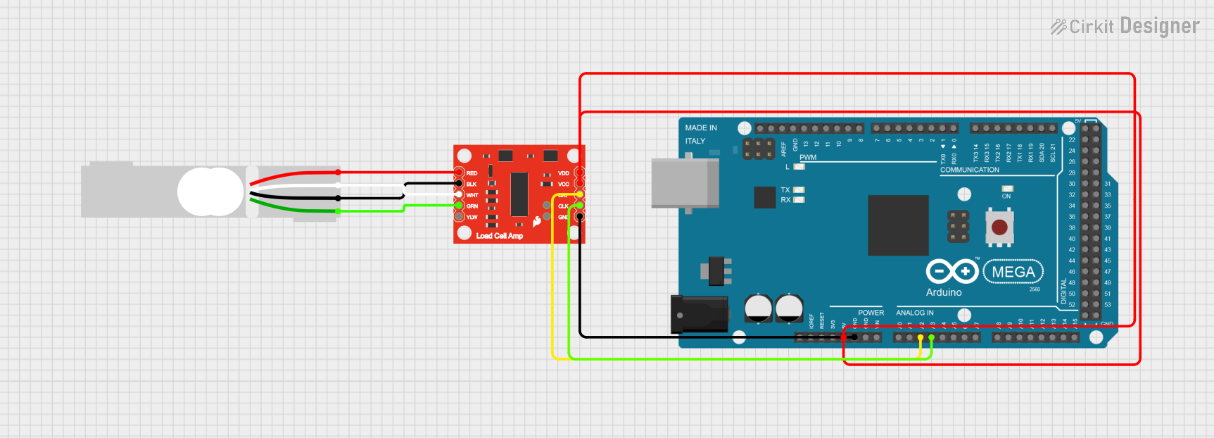
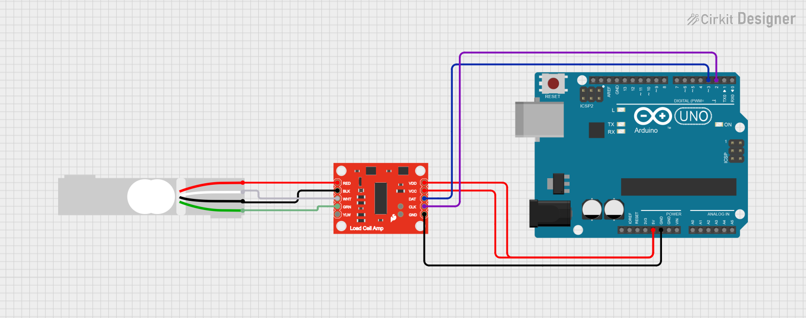
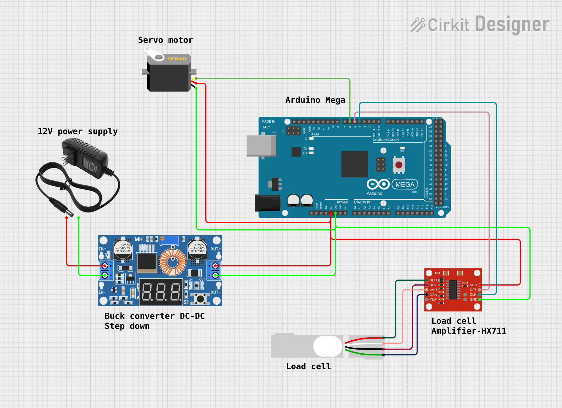
Explore Projects Built with SparkFun Load Cell Amplifier - HX711
Technical Specifications
Key Technical Details
- Supply Voltage (VCC): 2.6V to 5.5V
- Operating Current: < 1.5mA
- Selectable 10SPS or 80SPS output data rate
- Selectable gain of 32, 64, and 128
- On-chip power supply regulator for load-cell and ADC analog power supply
- On-chip oscillator requiring no external component with optional external crystal
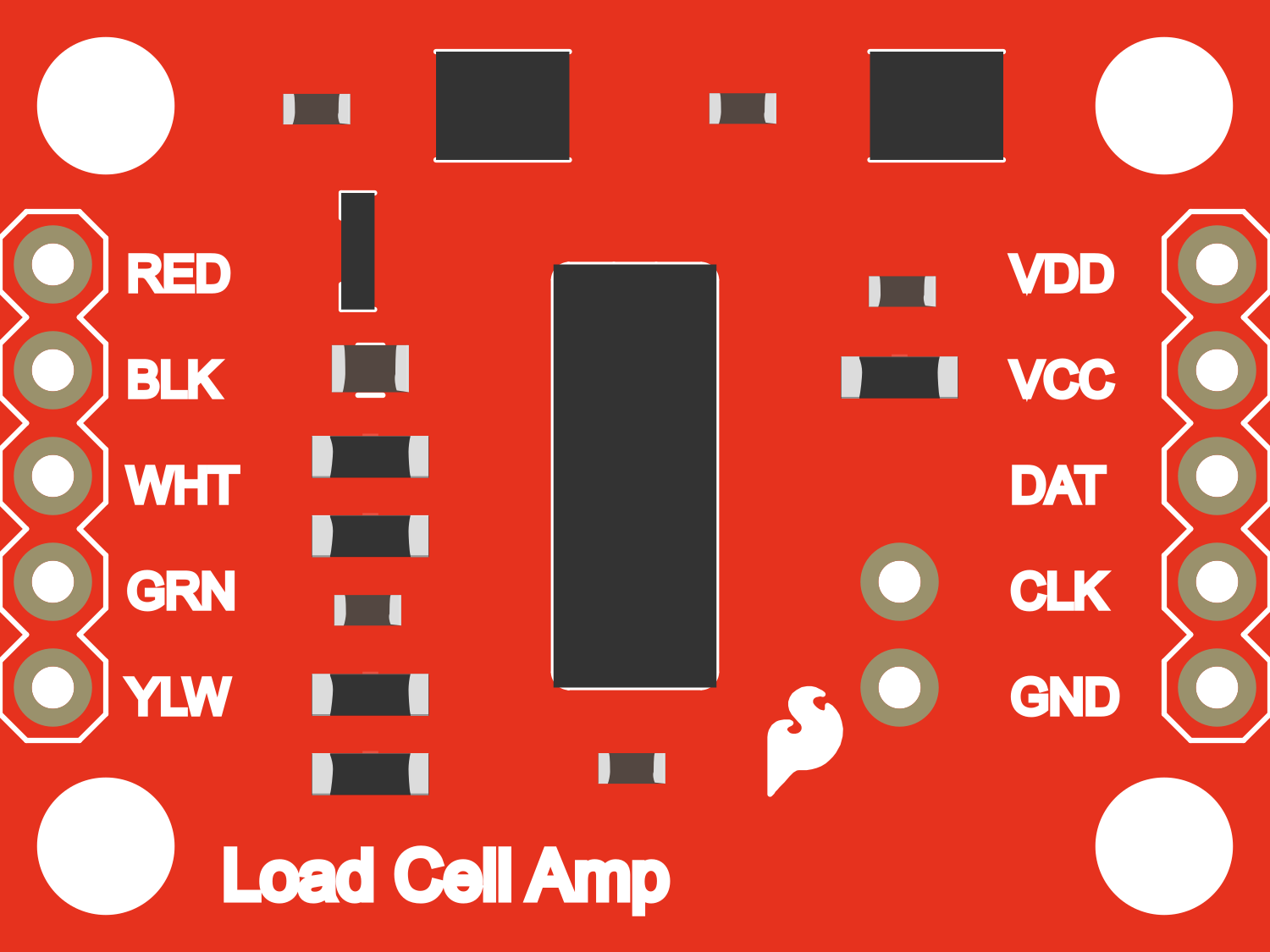
Pin Configuration and Descriptions
| Pin Name | Description |
|---|---|
| VCC | Power supply (2.6V to 5.5V) |
| GND | Ground |
| DT | Data output from HX711 to microcontroller |
| SCK | Serial Clock Input |
| E+ | Excitation+ for load cell |
| E- | Excitation- for load cell |
| A+ | Channel A positive input |
| A- | Channel A negative input |
| B+ | Channel B positive input (optional use) |
| B- | Channel B negative input (optional use) |
Usage Instructions
Interfacing with a Microcontroller
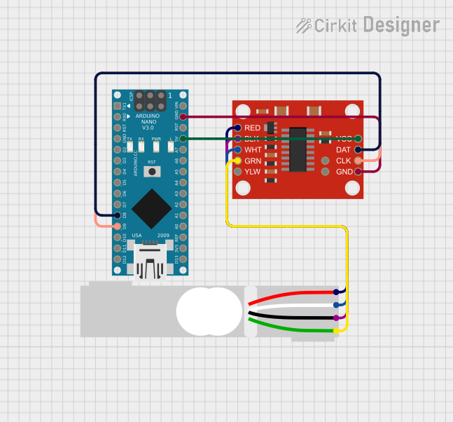
Connecting the Load Cell:
- Connect the load cell wires to the HX711 board's E+, E-, A+, and A- pins.
- Ensure that the load cell's excitation and signal wires are connected correctly.
Powering the HX711:
- Connect VCC to the microcontroller's 3.3V or 5V output.
- Connect GND to the microcontroller's ground.
Data Communication:
- Connect DT and SCK pins to digital I/O pins on the microcontroller.
Important Considerations and Best Practices
- Use a stable power supply to minimize noise in measurements.
- Keep the wires between the HX711 and the load cell as short as possible to reduce electromagnetic interference.
- Calibrate the load cell with known weights to ensure accurate readings.
- Implement proper filtering in software to smooth out jitter in the data.
Example Code for Arduino UNO
#include "HX711.h"

// HX711 circuit wiring
const int LOADCELL_DOUT_PIN = 3;
const int LOADCELL_SCK_PIN = 2;

HX711 scale;

void setup() {
  Serial.begin(9600);
  scale.begin(LOADCELL_DOUT_PIN, LOADCELL_SCK_PIN);
}

void loop() {
  if (scale.is_ready()) {
    long reading = scale.read();
    Serial.print("Reading: ");
    Serial.println(reading);
  } else {
    Serial.println("HX711 not found.");
  }
}
Troubleshooting and FAQs
Common Issues
- Inaccurate Readings: Ensure the load cell is calibrated correctly. Check for loose connections and ensure the HX711 is not experiencing power supply noise.
- No Data Output: Verify that the DT and SCK pins are connected properly and that the microcontroller is configured to the correct pins.
- Negative Readings: This can occur if the load cell wires are connected in reverse. Check the wiring against the load cell datasheet.
Solutions and Tips
- Calibration: Use a known weight to calibrate the scale. Adjust the calibration factor in the code accordingly.
- Stable Setup: Ensure the load cell is mounted securely and that the surface it is on is stable and level.
- Filtering: Implement a moving average or median filter in your code to reduce noise in the readings.
FAQs
Q: Can I use multiple HX711 boards with one microcontroller? A: Yes, you can use multiple HX711 boards by connecting each one to different digital I/O pins on the microcontroller.
Q: How do I change the gain or data rate of the HX711? A: The gain and data rate can be set through the library functions provided by the HX711 library. Refer to the library documentation for specific instructions.
Q: What is the maximum weight the HX711 can measure? A: The maximum weight the HX711 can measure depends on the load cell's capacity. The HX711 is an ADC that reads the electrical signal from the load cell, which varies based on the load cell's specifications.