Cirkit Designer Logo
Cirkit Designer
Your all-in-one circuit design IDE
Home / 
Component Documentation

How to Use Adafruit MLX90395: Examples, Pinouts, and Specs

Image of Adafruit MLX90395
Cirkit Designer LogoDesign with Adafruit MLX90395 in Cirkit Designer

Introduction

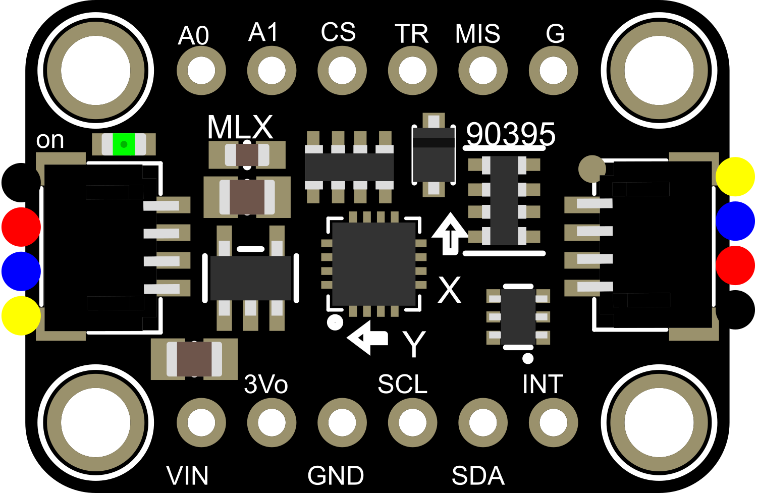
The Adafruit MLX90395 is a sophisticated magnetometer module capable of measuring magnetic fields in three dimensions. Utilizing the Melexis MLX90395 magnetic field sensor, this module offers precise and reliable readings, making it an ideal choice for a wide range of applications including compass navigation, position sensing, and motion detection.

Explore Projects Built with Adafruit MLX90395

Use Cirkit Designer to design, explore, and prototype these projects online. Some projects support real-time simulation. Click "Open Project" to start designing instantly!
Battery-Powered Sensor Hub with Adafruit QT Py RP2040 and OLED Display
Image of 512: A project utilizing Adafruit MLX90395 in a practical application
This circuit features an Adafruit QT Py RP2040 microcontroller interfacing with an MPU-6050 accelerometer, an Adafruit APDS-9960 sensor, and a 0.96" OLED display via I2C communication. It is powered by a 3.7V LiPo battery and includes a green LED with a current-limiting resistor connected to an analog pin of the microcontroller.
Cirkit Designer LogoOpen Project in Cirkit Designer
Battery-Powered Smart Sensor Hub with Adafruit QT Py RP2040
Image of wearable final: A project utilizing Adafruit MLX90395 in a practical application
This circuit features an Adafruit QT Py RP2040 microcontroller interfaced with an APDS9960 proximity sensor, an MPU6050 accelerometer and gyroscope, and an OLED display via I2C communication. It also includes a buzzer controlled by the microcontroller and is powered by a 3.7V LiPo battery with a toggle switch for power control.
Cirkit Designer LogoOpen Project in Cirkit Designer
Adafruit MPU6050 and VL6180X Sensor Interface with Servo Control
Image of wire: A project utilizing Adafruit MLX90395 in a practical application
This circuit features an Adafruit QT Py microcontroller interfaced with an Adafruit MPU6050 6-axis accelerometer/gyroscope and an Adafruit VL6180X Time of Flight (ToF) distance sensor, both connected via I2C communication. The QT Py also controls a Servomotor SG90, likely for physical actuation based on sensor inputs. The embedded code initializes the sensors, reads their data, and outputs the readings to a serial monitor, with the potential for motion control based on the sensor feedback.
Cirkit Designer LogoOpen Project in Cirkit Designer
Remote-Controlled Drone with Motion Sensing Capabilities
Image of melty: A project utilizing Adafruit MLX90395 in a practical application
This circuit is designed for motion control and telemetry in a small vehicle or drone. It includes an Adafruit ADXL345 accelerometer interfaced with a SparkFun Pro Micro microcontroller for motion sensing. The circuit also features two Electronic Speed Controllers (ESCs) to drive motors, a step-up voltage regulator to stabilize power supply from a Lipo battery, and a flysky mini receiver to receive control signals from a remote transmitter.
Cirkit Designer LogoOpen Project in Cirkit Designer

Explore Projects Built with Adafruit MLX90395

Use Cirkit Designer to design, explore, and prototype these projects online. Some projects support real-time simulation. Click "Open Project" to start designing instantly!
Image of 512: A project utilizing Adafruit MLX90395 in a practical application
Battery-Powered Sensor Hub with Adafruit QT Py RP2040 and OLED Display
This circuit features an Adafruit QT Py RP2040 microcontroller interfacing with an MPU-6050 accelerometer, an Adafruit APDS-9960 sensor, and a 0.96" OLED display via I2C communication. It is powered by a 3.7V LiPo battery and includes a green LED with a current-limiting resistor connected to an analog pin of the microcontroller.
Cirkit Designer LogoOpen Project in Cirkit Designer
Image of wearable final: A project utilizing Adafruit MLX90395 in a practical application
Battery-Powered Smart Sensor Hub with Adafruit QT Py RP2040
This circuit features an Adafruit QT Py RP2040 microcontroller interfaced with an APDS9960 proximity sensor, an MPU6050 accelerometer and gyroscope, and an OLED display via I2C communication. It also includes a buzzer controlled by the microcontroller and is powered by a 3.7V LiPo battery with a toggle switch for power control.
Cirkit Designer LogoOpen Project in Cirkit Designer
Image of wire: A project utilizing Adafruit MLX90395 in a practical application
Adafruit MPU6050 and VL6180X Sensor Interface with Servo Control
This circuit features an Adafruit QT Py microcontroller interfaced with an Adafruit MPU6050 6-axis accelerometer/gyroscope and an Adafruit VL6180X Time of Flight (ToF) distance sensor, both connected via I2C communication. The QT Py also controls a Servomotor SG90, likely for physical actuation based on sensor inputs. The embedded code initializes the sensors, reads their data, and outputs the readings to a serial monitor, with the potential for motion control based on the sensor feedback.
Cirkit Designer LogoOpen Project in Cirkit Designer
Image of melty: A project utilizing Adafruit MLX90395 in a practical application
Remote-Controlled Drone with Motion Sensing Capabilities
This circuit is designed for motion control and telemetry in a small vehicle or drone. It includes an Adafruit ADXL345 accelerometer interfaced with a SparkFun Pro Micro microcontroller for motion sensing. The circuit also features two Electronic Speed Controllers (ESCs) to drive motors, a step-up voltage regulator to stabilize power supply from a Lipo battery, and a flysky mini receiver to receive control signals from a remote transmitter.
Cirkit Designer LogoOpen Project in Cirkit Designer

Common Applications and Use Cases

  • Electronic compasses for navigation
  • Metal detection for security systems
  • Position and motion sensing in robotics
  • User interface controls (e.g., jog wheels, knobs)
  • Magnetic field mapping and visualization

Technical Specifications

The Adafruit MLX90395 magnetometer module is characterized by the following technical specifications:

Specification Value/Description
Operating Voltage 2.2V to 3.6V
Current Consumption 100 μA (typical)
Measurement Range ±5 mT per axis
Resolution 0.161 μT
Communication I2C (up to 1 MHz), SPI (up to 10 MHz)
Operating Temperature -40°C to 85°C
Dimensions 17.8mm x 15.3mm x 2.6mm (LxWxH)

Pin Configuration and Descriptions

Pin Number Name Description
1 VIN Supply voltage (2.2V to 3.6V)
2 GND Ground
3 SCL I2C clock (also acts as SPI clock)
4 SDA I2C data (also acts as SPI MOSI)
5 SDO SPI data output (also acts as SPI MISO)
6 CS SPI chip select (active low)
7 INT Interrupt pin (active low)

Usage Instructions

Integrating with a Circuit

To use the Adafruit MLX90395 magnetometer module in a circuit:

  1. Connect the VIN pin to a 2.2V to 3.6V power supply.
  2. Attach the GND pin to the common ground in your circuit.
  3. For I2C communication, connect the SCL and SDA pins to the corresponding I2C clock and data lines on your microcontroller.
  4. For SPI communication, connect SCL, SDA, and SDO to the SPI clock, MOSI, and MISO lines respectively, and the CS pin to a digital output for chip select.

Important Considerations and Best Practices

  • Ensure that the power supply is within the specified voltage range to prevent damage.
  • Use pull-up resistors on the I2C lines if they are not already present on the microcontroller board.
  • Keep the magnetometer away from strong magnetic fields that exceed the measurement range.
  • For accurate readings, calibrate the magnetometer in the final installation environment.

Example Code for Arduino UNO

Below is an example code snippet for interfacing the Adafruit MLX90395 with an Arduino UNO using the I2C protocol. Ensure you have installed the appropriate Adafruit MLX90395 library before uploading the code to the Arduino.

#include <Wire.h>
#include <Adafruit_MLX90395.h>

Adafruit_MLX90395 mlx;

void setup() {
  Serial.begin(9600);
  // Initialize the MLX90395
  if (!mlx.begin_I2C()) {
    Serial.println("Failed to find MLX90395 chip");
    while (1) { delay(10); }
  }
  Serial.println("MLX90395 Found!");
}

void loop() {
  mlx.readData();
  // Print out the X, Y, Z values
  Serial.print("X: "); Serial.print(mlx.x, 4); Serial.print(" uT, ");
  Serial.print("Y: "); Serial.print(mlx.y, 4); Serial.print(" uT, ");
  Serial.print("Z: "); Serial.print(mlx.z, 4); Serial.println(" uT");
  
  // Delay between readings
  delay(500);
}

Troubleshooting and FAQs

Common Issues

  • No data or communication errors: Ensure that the wiring is correct and that the correct voltage is applied. Check for proper soldering and connections.
  • Inaccurate readings: Calibrate the sensor, and make sure it is not near any strong magnets or ferrous materials that could affect the readings.

Solutions and Tips for Troubleshooting

  • Sensor not detected: Check the I2C or SPI connections and ensure that the correct address or chip select pin is being used.
  • Fluctuating readings: Implement a software filter or averaging algorithm to stabilize the readings.

FAQs

Q: Can the MLX90395 be used with a 5V microcontroller? A: Yes, but ensure that the VIN pin is connected to a voltage within the 2.2V to 3.6V range. Use level shifters for I2C or SPI lines if necessary.

Q: How can I calibrate the magnetometer? A: Calibration typically involves rotating the sensor in all three axes and using software to map the raw readings to a calibrated scale.

Q: What is the maximum sampling rate of the MLX90395? A: The maximum sampling rate depends on the communication protocol used (I2C or SPI) and the specific settings of the sensor. Refer to the datasheet for detailed timing information.

This documentation provides a comprehensive guide to using the Adafruit MLX90395 magnetometer module. For further details and advanced usage, consult the datasheet and additional resources provided by Adafruit.