How to Use Exhaust Fan: Examples, Pinouts, and Specs
Introduction
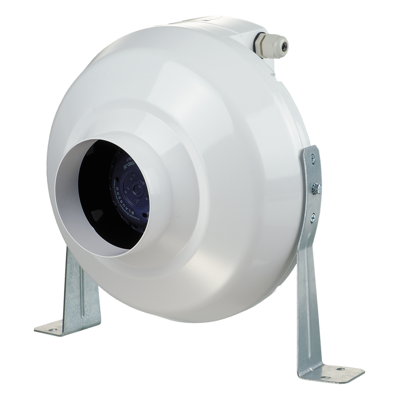
The Exhaust Fan is a device designed to ventilate and remove stale air, smoke, or fumes from an area. It is commonly used in kitchens, bathrooms, and industrial settings to maintain air quality and ensure a safe and comfortable environment. This documentation provides detailed information on the technical specifications, usage instructions, and troubleshooting tips for the Exhaust Fan.
Explore Projects Built with Exhaust Fan
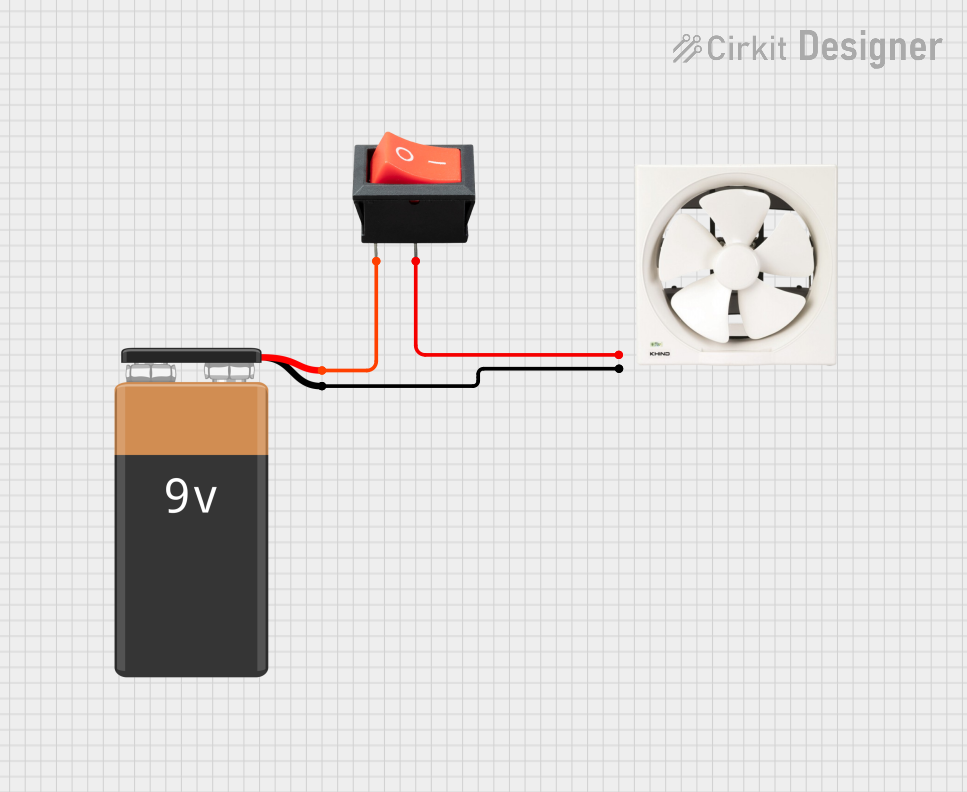
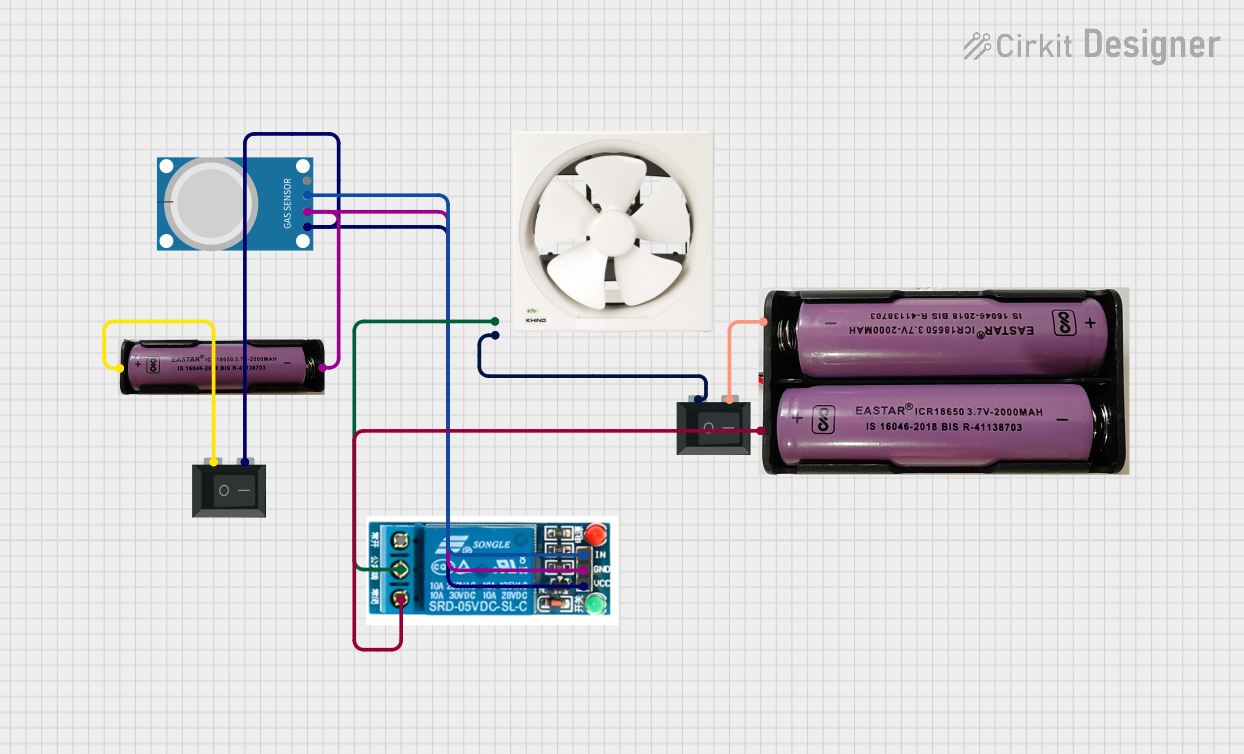
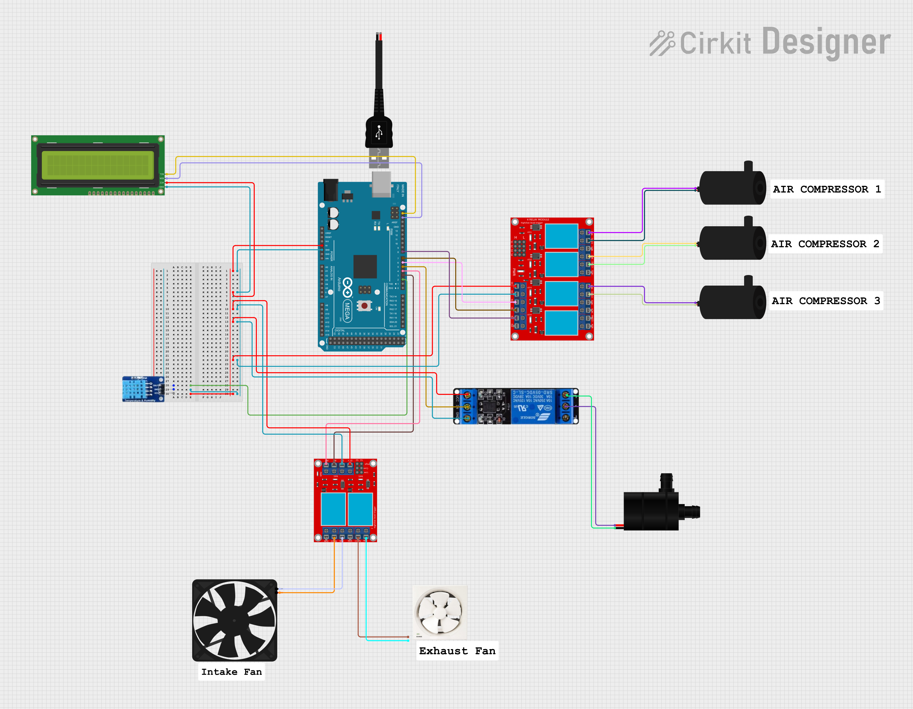
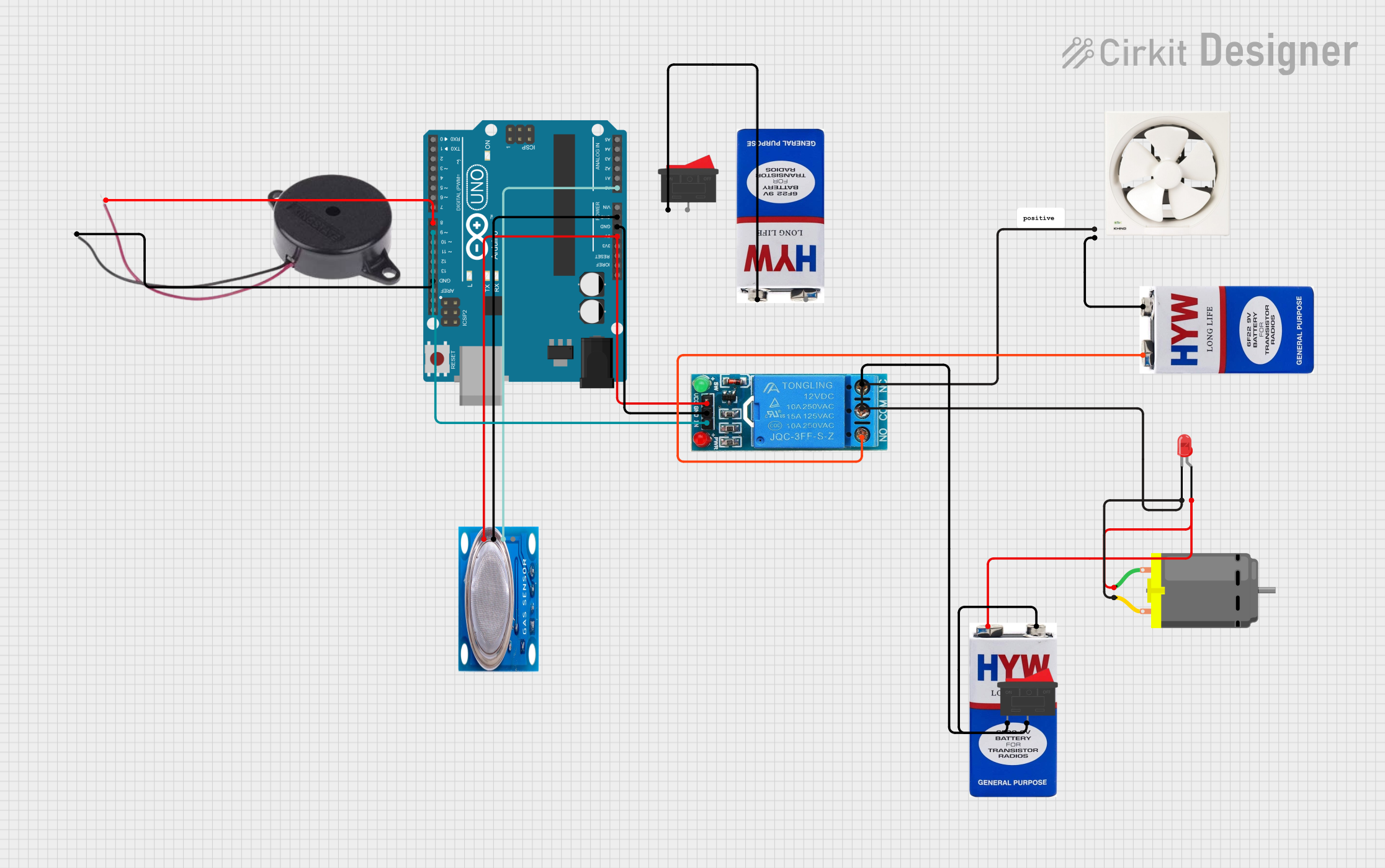
Explore Projects Built with Exhaust Fan
Technical Specifications
Key Technical Details
| Parameter | Value |
|---|---|
| Voltage Rating | 220V AC |
| Current Rating | 0.5A |
| Power Rating | 110W |
| Airflow Capacity | 300 CFM (Cubic Feet per Minute) |
| Noise Level | 45 dB |
| Operating Temperature Range | -10°C to 50°C |
| Dimensions | 300mm x 300mm x 150mm |
| Weight | 2.5 kg |
Pin Configuration and Descriptions
| Pin Number | Pin Name | Description |
|---|---|---|
| 1 | L | Live wire connection (220V AC) |
| 2 | N | Neutral wire connection |
| 3 | G | Ground connection |
Usage Instructions
How to Use the Exhaust Fan in a Circuit
- Safety First: Ensure the power supply is turned off before making any connections.
- Wiring: Connect the Live (L) wire to the 220V AC supply, the Neutral (N) wire to the neutral line, and the Ground (G) wire to the ground.
- Mounting: Securely mount the exhaust fan in the desired location using appropriate screws and brackets.
- Power On: Once all connections are made and the fan is securely mounted, turn on the power supply.
Important Considerations and Best Practices
- Proper Ventilation: Ensure that the exhaust fan is installed in a location where it can effectively ventilate the area.
- Regular Maintenance: Clean the fan blades and housing regularly to maintain optimal performance.
- Avoid Obstructions: Make sure there are no obstructions blocking the airflow of the exhaust fan.
- Check Connections: Periodically check the electrical connections to ensure they are secure and free from corrosion.
Troubleshooting and FAQs
Common Issues and Solutions
Fan Not Turning On
- Solution: Check the power supply and ensure that the live, neutral, and ground wires are properly connected. Verify that the power switch is turned on.
Excessive Noise
- Solution: Clean the fan blades and housing to remove any dust or debris. Ensure that the fan is securely mounted and not vibrating against any surfaces.
Reduced Airflow
- Solution: Check for any obstructions in the airflow path. Clean the fan blades and housing to ensure optimal performance.
Overheating
- Solution: Ensure that the fan is not operating in an environment with temperatures exceeding the specified operating range. Check for any obstructions that may be causing the fan to work harder than necessary.
FAQs
Q1: Can the exhaust fan be used with an Arduino UNO? A1: Yes, the exhaust fan can be controlled using an Arduino UNO with the help of a relay module. Below is an example code to control the exhaust fan using an Arduino UNO and a relay module.
// Example code to control an exhaust fan using Arduino UNO and a relay module

const int relayPin = 7; // Pin connected to the relay module

void setup() {
  pinMode(relayPin, OUTPUT); // Set the relay pin as an output
  digitalWrite(relayPin, LOW); // Ensure the relay is off initially
}

void loop() {
  digitalWrite(relayPin, HIGH); // Turn on the exhaust fan
  delay(10000); // Keep the fan on for 10 seconds
  digitalWrite(relayPin, LOW); // Turn off the exhaust fan
  delay(10000); // Keep the fan off for 10 seconds
}
Q2: What is the maximum operating temperature for the exhaust fan? A2: The maximum operating temperature for the exhaust fan is 50°C.
Q3: How often should the exhaust fan be cleaned? A3: It is recommended to clean the exhaust fan at least once every three months to maintain optimal performance.
Q4: Can the exhaust fan be used in a humid environment? A4: Yes, the exhaust fan is designed to operate in environments with high humidity, such as bathrooms and kitchens.
By following this documentation, users can effectively utilize the Exhaust Fan in various applications, ensuring proper ventilation and air quality.